Continue to Site

Welcome to EDAboard.com

Welcome to our site! EDAboard.com is an international Electronics Discussion Forum focused on EDA software, circuits, schematics, books, theory, papers, asic, pld, 8051, DSP, Network, RF, Analog Design, PCB, Service Manuals... and a whole lot more! To participate you need to register. Registration is free. Click here to register now.

extending LF (125khz or 134khz) RFID reader to 50cm or 1m

Status
Not open for further replies.

robotnik

Newbie level 3
Joined
Feb 10, 2012
Messages
3
Helped
0
Reputation
0
Reaction score
0
Trophy points
1,281
Location
Somerset, UK
Activity points
1,311
Hi all,

please be kind this is my first post, I hope I am in the right place etc. etc.

So I am building an RFID reader which will need to be able to read accurately and consistently at 50 -70 cm distance. I am currently using the atmel u2270b base station IC
and have successfully read and decoded the 128 bit biphase signal returned by my tags.

Nothing in the data sheet says anything about going above about 20 cm, but I appears to be possible to read at greater distances than this as I have seen hardware doing it (not with u2270b).

I am currently thinking of amplifying the antenna driver signal to increase the field strength, but am unsure of likelihood of success, or whether this is a stupid idea.

Does anyone have any ideas about how I could get this done. i.e other ICs, discrete components or any other advice.

thank you.


p.s before you tell me to use a higher frequency RFID system, I cannot, this must be done with LF (134khz) magnetic induction type passive RFID.
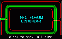
 

First step would be to calculate the minimal amount of ampere-windings for a given reader coil size, presumed you know the required field strength at the target. Then design a respective driver.

The second step ist to determine the expectable received load modulation, if it's sufficiently above carrier noise level. Otherwise you need to design a compensating dual coil coupler.
 
Hi, thanks for the reply.

I am making progress with my own driver and demodulation, getting better read distance than with the u2270b chips I was using before, and I learnt something.

I have a question regarding the "compensating dual coil coupler". I am assuming that this is something like a pair of coils wound in opposing directions and with opposite drivers, so that the field produced is in the same direction, but any noise picked up is equal and opposite so it cancels itself out. similar to the way humbucking guitar pickups work.

Is this the right kind of idea, or am I way off the mark? Also do you know of any literature that you could point me towards.

Many thanks.

ps. btw this is a ASK RFID system.
 

I would suggest the way to maximize your range of this transponder is to use a Q> 100 with the largest inductance you can get with ferrite & flat coil winding methods so that the SRF is well above 150KH so that it may be tuned to 134kHz. Also minimize your ESR so you can maximize your Tx Power and Q. Unfortunately this may increase costs. Consider the oval flat AM antenna's used in old radios but make it bigger. Also consider use of the long Ferrite tuned antenna for Rx with high µ.

I see Omron can obtain 2m transponder range.

I might also suggest an autotransformer arrangement like dual coil but closer coupling with large loops and high SRF. Consider old automotive ignition coils had an SRF above 20Khz with a voltage gain of > 1000:1... scale that to get 100:1 @ 134KHz. with amplification for Tx and amplification for separate Rx using autotransformer loop coils to match impedance to free space with high Q.
 
Last edited:
Hi there, thanks for the pointers.

That's definitely something for me to get started with, I'll let you know of my success. Do you know of any good texts or websites for a good basis in all this stuff (inductor design), as its a bit new to me and I'm not sure quite where to begin.

Many thanks.
 

I would suggest the way to maximize your range of this transponder is to use a Q> 100
Considering the basic parameters of the involved RFID systems is suggested. There are things like data rate and modulation bandwidth. The U2207 reference circuit reduces the reader coil Q purposeful to about 15.

As previously mentioned, the nominal field strength expected by your tags is the first design parameter you definitely should know. Otherwise it's just trial and error method.

Generally, a long distance reader can use large field strengths in a "brute force" manner as long it's not obliged to keep legal RF and EMC standards.

I mentioned carrier noise as a possible problem and compensating coil designs as a possible solution. A basic RFID system uses a common coil for send and receive. In return, the send signal will be present at the receiver without attenuation. Because all passive low frequency RFID is essentially load modulation, carrier noise is at risk to squelch low level tag signal.

A compensating coil topology tries to reduce the carrier level at the receiver coil without losing too much tag signal. As an example, see a for NFC (13.56 MHz). Its main purpose is to get the tag generated load modulation signal separated from carrier for measurement. A reader IC is basically prepared to detect the tag signal "under" a large carrier signal, so the compensating coils won't be needed if you don't approach actual noise limits.

 
Status
Not open for further replies.

Part and Inventory Search

Welcome to EDABoard.com

Sponsor

Back
Top