anonymous.
Junior Member level 3
hi guys,
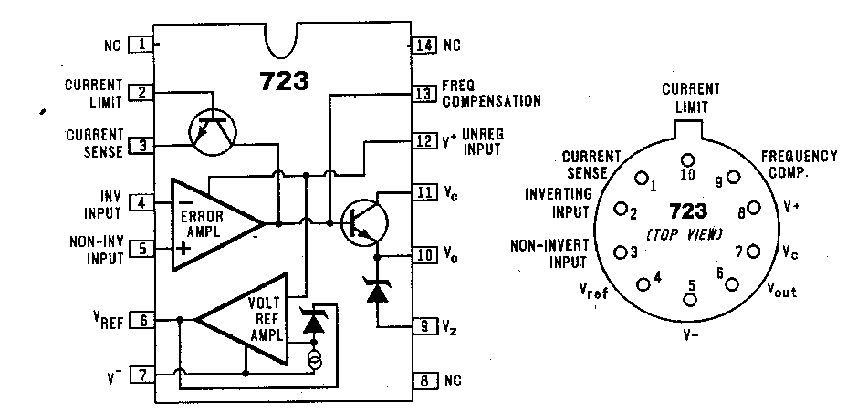
i want to make a power supply using LM723 but i cant understand how to use it. I dont know what the pin functions are (current limit , current sense , Vz , .....)
can anyone tell me how to use this IC ?? or any online tutorial .
thanks.
i want to make a power supply using LM723 but i cant understand how to use it. I dont know what the pin functions are (current limit , current sense , Vz , .....)
can anyone tell me how to use this IC ?? or any online tutorial .
thanks.