Continue to Site

Welcome to EDAboard.com

Welcome to our site! EDAboard.com is an international Electronics Discussion Forum focused on EDA software, circuits, schematics, books, theory, papers, asic, pld, 8051, DSP, Network, RF, Analog Design, PCB, Service Manuals... and a whole lot more! To participate you need to register. Registration is free. Click here to register now.

hi how can i improve brightness in 5x7 dotmatrix display????

Status
Not open for further replies.

Shanthakumarji

Newbie level 5
Joined
Mar 26, 2012
Messages
8
Helped
0
Reputation
0
Reaction score
0
Trophy points
1,281
Location
Chennai,India
Activity points
1,332
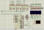
our project is a 80 coloumns and 7 rows(80X7=20 no of 5x7) dot matrix display.
i this we are using 74Hc595 for shifting.
we use Pic 16F877A. and 12 Mhz crystal.
we are also sending the display message via RS232.

but we are not getting brightness...
when we increase the number of letters we are getting flickering problem, and less brightness, we are giving 200micro seconds delay for shifting each coloum.

we are sending one in MC and Zero in 595.
so we are sourcing the controller.
we cant get brightness so please help us....View attachment 5x7dotmatrix.txt 5x7dotmatrix.JPG
 

You can increase the brightness by increasing the LED peak current. Check the datasheet for the peak current and average current that the LED's can handle. Make sure not to exceed the peak current, otherwise set the current limiting resistor to allow the maximum average current.

For instance, if the LED's can have 20mA average forward current, and you are pulsing this for a total of, say 10ms every second, you could set a current of 20mA x 1/0.01 = 2 amps, but your LED's might not be able to go that high, neither will your driver chips, so set a lower compromise limit.
 
Also, a filter in front can help too (dramatically sometimes). It's not increasing brightness of course, but it does improve the visibility of it.
 

Thanks all...


FoxyRick i have one doubt...
20mA x 1/0.01 = 2 amps

how u do this calculation ???

can u explain this ?
 

For instance, if the LED's can have 20mA average forward current, and you are pulsing this for a total of, say 10ms every second, you could set a current of 20mA x 1/0.01 = 2 amps, but your LED's might not be able to go that high, neither will your driver chips, so set a lower compromise limit.

I don't think that a calculation like this is valid , what you are saying is that for a 20mA led you can use 2A for 10ms (1sec/10ms=100*20mA=2A) but you don't take into consideration the peak forward current which is given in the absolute max section of the datasheet of the led.
 

I did mention that, twice.

You can increase the brightness by increasing the LED peak current. Check the datasheet for the peak current and average current that the LED's can handle. Make sure not to exceed the peak current, otherwise set the current limiting resistor to allow the maximum average current.

For instance, if the LED's can have 20mA average forward current, and you are pulsing this for a total of, say 10ms every second, you could set a current of 20mA x 1/0.01 = 2 amps, but your LED's might not be able to go that high, neither will your driver chips, so set a lower compromise limit.
 

Yes you did , but my brain was not working :roll:... sorry.
 

Change your method. Use HC595 as column value and Port B as Row value, so the LED will on in 1/7 of total power. Your design, the LED will on in 1/80 of total power. Then you will need high current transistor to drive 80 LEDs.
 

did u see my hardware in the attachment ????

i am shifting columns in 595 and passing the values in portB.

now u r asking me to give the value to portB single pin via 595 and shift rows ?
 

Your method, draw first column and another 79 columns are off, then process next column and the others are off, continue till 80th column.
I mean draw first row and another 7 rows are off, then process next row and the others are off, continue till 8th row.
Have you got it?

untitled.GIF

Code:
e=0xfe; // or e=0x80
for(a=0;a<8;a++) //8 rows
{
  for(b=0;b<12;b++)  //12 chars
  {
    for(c=0;c<5;c++)//5 columns 
    {
      d=matrix[arr[b]-0x20][c];
      d>>=a;
      d&=1;
      DS=d;
      SHCP=1;
      SHCP=0;
    };
    DS=0;	//add space between each character
    SHCP=1;
    SHCP=0;
  };  
  e>>=a;
  e|=0x80; //or e&=0x7f
  STCP=1;
  STCP=0;
  PORTB=e;
  delay;
};
 
Last edited:
hi archzone... your info was very useful. but i have one doubt ,in this method you are displaying simply 12 characters . that makes the letters in the LED stable. suppose if i want to enter more than 12 letters and make the letters scroll ,what shall i do? give me some idea in code.
 

this is a basic way to make display move (moving each character). You can learn from it, improve it to moving each column

Code:
  unsigned char arr[]="            this is an example how to show long message at dotmatrix display            ";
  while(1)
  {
    g=0; //start at position 0 of message
    while (arr[g]!='\0')
    {
      for (f=0;f<100;f++)  //number of loop before start at next position of message
      {
        e=0x7f; // or e=0x80
        for(a=0;a<8;a++) //8 rows
        {
          for(b=0;b<12;b++)  //12 chars
          {
            for(c=0;c<5;c++)//5 columns 
            {
              d=matrix[arr[b+g]-0x20][c];
              d>>=a;
              d&=1;
              DS=d;
              SHCP=1;
              SHCP=0;
            };
            DS=0;	//add space between each character
            SHCP=1;
            SHCP=0;
          };  
          e>>=a;
          e|=0x80; //or e&=0x7f
          STCP=1;
          STCP=0;
          PORTB=e;
          delay;
        };
      };
      g++; //start at next position of message
    };
  };
 
Thanks for ur info...

When i run this in Proteus i got perfect output..
but when i run this in my kit i got flickering problem...
i gave delay of 1ms ..
for clock pulse in STCP and SHCP i give 1 microsecond delay...
i tired increasing and decreasing the delay but got the same problem............:!:
 

Yes, you are right. It's timing problem. Try decrease delay about 500 us. Good display need refresh rate > 50 Hz or < 20 ms. Because we have 8 rows, each row must be switched less than 2.5 ms. Although you set 1 ms delay, but RAM/EEPROM reading, clocking, shifting add more time processing. Use maximum speed of processor and clock multiplier.
 
Status
Not open for further replies.

Part and Inventory Search

Welcome to EDABoard.com

Sponsor

Back
Top