Continue to Site

Welcome to EDAboard.com

Welcome to our site! EDAboard.com is an international Electronics Discussion Forum focused on EDA software, circuits, schematics, books, theory, papers, asic, pld, 8051, DSP, Network, RF, Analog Design, PCB, Service Manuals... and a whole lot more! To participate you need to register. Registration is free. Click here to register now.

low dropout regulator

Status
Not open for further replies.

lovaraju.ch

Newbie level 6
Joined
Mar 8, 2012
Messages
13
Helped
0
Reputation
0
Reaction score
0
Trophy points
1,281
Activity points
1,382
Dear all,

I am designing a low dropout regulator for 1 mA to 100 mA of load current. when the load current is 1 mA the pass transistor (pmos) is going into the subthreshold region and due to this, overshoot and undershoot are increased . so could you please tell me how to avoid subthreshold operation of pass transistor at 1 mA of load current.

waiting for your valueble reply
thanks...
 

Dear lovaraju.ch
Hi
What kind of LDO ? can you attach your schematic ? and Why with mosfet ?? you can use a simple BJT .
Best Wishes
Goldsmith
 

Dear Goldsmith
thank you for your valuable response
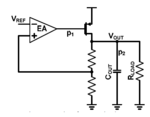
I am designing a output capacitor less LDO. LDO.png.
here I uploaded my schematic.
waiting for your reply...
 

It has a big problem ! change the inverting and non inverting pines of op amp . to provide feed back .
It has positive feed back now and it is not good for a power supply .
Respect
Goldsmith
 

It has positive feed back now ....

I like to remind you that the sign of feedback is determined by the complete loop and not by the sign of the opamp input node.
Thus, there is negative feedback as required for an LDO (due to transistor sign inversion).
 
Hi gold,
I guess the feedbcak is proper.
Hi lovaraju.ch
I guess you have made the dominant pole at the o/p of the OTA. In that case, when the o/p current decreases, the output pole moves towards the dominant pole, reduction in Phase margin. But I didnt understand how subthreshold region operation is a problem.
 
Hi dear LvW And Hi Dear analogbeginer
Thank you for all of your remarks .
Yes you're absolutely right .
I didn't see the LDO such as this , until now , but i think if he try to use a fet or a bjt , as a series pass element it will be better , isn't it ?
Best regards
Goldsmith
 

even though op amp has positive feed back, the overall feedback from input to output is negative feedback only. the above circuit is the basic circuit of LDO
 

hi dear analogbeginer

Actually the pass transistor is designed to operate at saturation region for 100 mA of load current. so to provide 100 mA of load current, the width of the pass transistor must be too large. so when load current decreases to 1 mA, due to high pass transistor width, it is going into the sub threshold region to provide 1 mA of load current. now the problem of sub threshold operation is that, the pass transistor responds slowly for load changes because its gm is low under sub threshold operation. so when the pass transistor is responding slowly, the overshoot and undershoot are very high when the load is changing with less slew-rate. this is the basic problem I had.
 

Hi,
First of all, gm effcieny is at the max in subthreshold when compared to saturation. If you are suggesting that it will respond slowly due to the parasitic cap due to the large device, then it shld be the same case as in saturation too.
 

dear analogbeginer

there are two cases for sub threshold operation for mos transistor.
1. when W/L ratio of transistor is changing for constant bias current: In this case if the transistor is operating in saturation region for particular bias current and for particular W/L ratio, then if we increase the W/L ratio of same transistor for same bias current, then this transistor will operate in sub threshold region and here gm is high for sub threshold transistor than saturated transistor
2. when bias current is changing for constant W/L ratio: In this case W/L is constant and bias current will be decreased. so whenever the bias current is decreased for constant W/L then transistor changes from saturation to sub threshold. In this case gm of sub threshold transistor is lower than saturated transistor.
Now our problem related to second point in this paragraph. here during 1 mA- 10 mA of load current transistor is sub threshold and during this region only i am getting large overshoot and undershoot. during 10-100 mA transient response is good.
 

Yes. I guess the earlier post said, gm efficieny is good in subthreshold & may not be the actual gm. Can you share AC/transient plots?
 

ac wise it is ok because pm is 50-75 degrees. here i attached one transient plot. in this plot time axis is 1 us/ divUntitled.png
 

Part of that transient may be the op amp being at the positive rail with no output current, and then having to slew to the proper voltage to turn on the transistor when the current starts increasing from zero. Look at the op amp output to see what it is doing.
 

dear crutschow

here load current never comes to zero. my load range is 1 mA to 100 mA and during this load range I had good phase margin, gain and bandwidth. If pass transistor had not gone into sub threshold at 1 mA, LDO would have regulated the voltage properly.
 

dear crutschow

yes. the op amp output is generated based on output voltage of LDO. when the output voltage spike is high then op amp is charging or discharging parasitic capacitor at gate of pass transistor very fast as we expected from normal LDO operation. here I have attached the output voltage of op amp along with output voltage of LDO
 

this is the output voltage of op amp along with output voltage of LDOUntitled1.png
 

From your transient plots, I believe you have the dominant pole at the opamp output rather than at the LDO output (Your load range also indicates that).
In this case, this is what you can expect. The transient response at light load will be sluggish firstly due to relatively high impedance at the output (lower bandwidth and in your case phase margin) secondly due to the slow response from the opamp. I dont think there is significant contribution from the pass transistor being in sub-threshold. If there is a LDO that always has it's pass transistor in strong inversion, then the specifications are very, very relaxed and you they wont find much use
 

Status
Not open for further replies.

Similar threads

Part and Inventory Search

Welcome to EDABoard.com

Sponsor

Back
Top