Continue to Site

Welcome to EDAboard.com

Welcome to our site! EDAboard.com is an international Electronics Discussion Forum focused on EDA software, circuits, schematics, books, theory, papers, asic, pld, 8051, DSP, Network, RF, Analog Design, PCB, Service Manuals... and a whole lot more! To participate you need to register. Registration is free. Click here to register now.

HELP! 18f4550 outputs 2.57V on pinouts, I want it to output 5v.

Status
Not open for further replies.

McFly123

Newbie level 6
Joined
Jan 21, 2012
Messages
14
Helped
2
Reputation
4
Reaction score
1
Trophy points
1,283
Activity points
1,393
We're using PIC18f4550 and we need to drive an ultrasonic sensor which needs 5V trigger to its Trig pin, but our PIC outputs only 2.57V.

//initialization

RD0_BIT = 1, // this only sends 2.57V to the ultrasonic sensor.
Delay_us(10);
RD0_BIT = 0;


.......
please help
 

Disconnect the ultrasonic sensor and check the pin's output voltage. If it reads 5V without a load connected, then the ultrasonic sensor is drawing too much current, and the PIC can't supply it. If that's the case, use the pin on the PIC to control a FET or BJT as a switch. Use that switch to toggle power to the sensor. Like this, but with your transducer instead of the LED and R3.
 
Make sunre that microcontroller pins are configured as digital, not analog. Most PIC micros have analog inputs on some port, which are set to be analog by default (one of the things I don't like about PCU MCU's)
 
Make sunre that microcontroller pins are configured as digital, not analog. Most PIC micros have analog inputs on some port, which are set to be analog by default (one of the things I don't like about PCU MCU's)

its now on DIgital, and BTW I hate this thing too... I'll try making the transistor switch above. thanks guys...
 

If you're sending continuous pulse at or around 50% duty cycle, then, it is your meter showing you 2.57V (the average voltage), whereas the actual voltage when output=1 is actually 5V. eg. If you're turning RD0 on, waiting 10us, turning RD0 off, waiting 10us, then turning it on again and so on, you have 50% duty cycle and your PIC goes from 0V to 5V and then back to 0V, staying at 5V for as long as it stays as 5V. So, the average voltage is (0.5*5) = 2.5V.

Did you try connecting the ultrasonic sensor? Do you know how much current you need? If it's higher than 15mA, it's better anyways to connect an NPN transistor or N-MOSFET to amplify the current.

Hope this helps.
Tahmid.
 

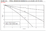
Notice the typical voltage drop when you source current from the PIC output, if you are pulling too much current you will see a high voltage drop

PIC16F_VOH-IOH.gif
 

Send specs of ultra.. is the sensor capacitance ?
maybe u need pullup resistor pic my be tri state, use mosfet not bipolar.
good luck
 

Specifications:
power supply :5V DC
quiescent current : <2mA
effectual angle: <15°
ranging distance : 2cm – 500 cm
resolution : 0.3 cm

the sensor we're using is HC-SR04.
http://jaktek.com/wp-content/uploads/2011/12/HC-SR04.pdf

we're still figuring this one out. we're trying to put delays so it could read the echo back... anyways I'll keep posting our progress.

thanks a lot guys...

---------- Post added at 22:09 ---------- Previous post was at 21:59 ----------

BTW to Tahmid, you're right, it was explained to me by a friend. now our problem is how to read the data at the echo pin. we dont want to use it for ranging. only we would like it to detect an obstacle. like if someone pass through the sensor... it would read 1 at the echo pin else 0.
 

    V

    Points: 2
    Helpful Answer Positive Rating
Use the microcontroller to measure the echo back. You can use the capture module or you could do without it. The formula is given. Determine how much distance you want to take.

According to the sequence chart, the output pulse width corresponding to distance is between 150us and 25ms, 38ms being output when there is no obstacle. Use the PIC to determine if the pulse width is between 150us and 25ms. If it is, then there is an obstacle. If it is not and it is between say 37ms and 39ms, then there is no obstacle. You can ignore this as well. However, you may include it just to be safe.

Hope this helps.
Tahmid.
 
i also need help... i want to communicate, serial camera to mcu and data will be save to sd card... someone please send me a circuit connection of my project... im using pic18f4550 mcu, and the source of my serial camera is 3.3v... some one help me...
 
Which serial camera are you using? What is the part number? Did you take a look at the datasheet? Did you get hold of the datasheet?
 
i also need help... i want to communicate, serial camera to mcu and data will be save to sd card... someone please send me a circuit connection of my project... im using pic18f4550 mcu, and the source of my serial camera is 3.3v... some one help me...

1) i understant the sonic unit gets external initiate signal to the other pins , and u dont have echo out ?
2) if u do have ocho out from sonic unit all u need is to take a picture right.
if so the then the process is too slow until the system will take a pic the intruder will be long gone.
3) u need to make your camera to record permanently and store data in mpu memory as frames and compare frames
once the memory that will be stored from example : address 1000-2000 when u reache 2000 u will overlap info in 1000, if u get intruder signal store all bytes 10 clips before the alarm up to 10 frames in a diiff mem location.
 
Do we have to read the Echo pin as Digital? or is it Analogue? @ Tahmid, I find ur post very helpful.

@dselec - The answer to ur first question is Yes.. but the camera is not part of our project.

thanks guys. I'll post if there's an improvement.
 
Disconnect Everything From the Micro-Controller and then send High to your respective Port..
And Check What is the Result..
High or Not..
This is the best way to solve ur problem..
Go Step by Step
 
Do we have to read the Echo pin as Digital? or is it Analogue? @ Tahmid, I find ur post very helpful.

@dselec - The answer to ur first question is Yes.. but the camera is not part of our project.

thanks guys. I'll post if there's an improvement.

www.elecfreaks.com/store/download/HC-SR04.pdf

The bottom of sheet 2 should give you a clear picture of the timing and pin usage of this device. Sheet 1 states that the ECHO output is a TTL signal, so I'd set up the MCU pin connected to ECHO as a Digital In, and the MCU pin connected to TRIGger as a Digital Out.

Also note their suggestion for a measurement window of >60 usec to prevent capturing additional echos from the previous pulse (gives the last ultrasonic pulse time to dissipate and disperse).
 
Echos which ? the unit gives out 40 khz 8 times with a short delay between each burst. that time is enough for reception the system is build this way.
so now once u got a trigger after the first or second burst (u decide when) if u get a echo u will know u have a real terger so get your camera going and keep recording and saving all the way until the 8 bursts end, that's all.
 

is any one help me in microC pro, file handling library... i want to save image in to my sd card, using ng mmc library and spi library in my microC pro... please someone help me for coding... please.... im using pic18f4550
 

Status
Not open for further replies.

Part and Inventory Search

Welcome to EDABoard.com

Sponsor

Back
Top