Continue to Site

Welcome to EDAboard.com

Welcome to our site! EDAboard.com is an international Electronics Discussion Forum focused on EDA software, circuits, schematics, books, theory, papers, asic, pld, 8051, DSP, Network, RF, Analog Design, PCB, Service Manuals... and a whole lot more! To participate you need to register. Registration is free. Click here to register now.

[SOLVED] Help in a circuit regarding IR receiver TSOP1738 and Buzzer

Status
Not open for further replies.

xpress_embedo

Advanced Member level 4
Joined
Jul 5, 2011
Messages
1,154
Helped
161
Reputation
396
Reaction score
189
Trophy points
1,353
Location
India
Activity points
10,591
I want to make a Circuit..which detects the IR Light and Blows a Buzzer when There is no Light...

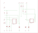
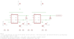
I had generated a 38Khz Frequency IR Light using 555 IC...
And Tries to detect it using TSOP1738..
Everything works fine for me...
Means Everything works Properly as per specified in Datasheet..

But i want to make a circuit ...
IR Trans ---------------> IR Receiver (Buzzer Will Not Blow)
IR Trans ----->| IR Receiver Will not Receive any thing (Buzzer Must Blow)
(Path Blocked)

Its a type of security system.. when some one passes through it must blow an alarm..

can any one suggest me a circuit in doin so...
 

I am not sure this will work, because you have not described the system you have in sufficient detail. If you are using an on/off modulated 38KHz carrier, then your receiver output is a series of pulses at about 1 KHz or whatever the modulation frequency is. In that case, a missing pulse detector will do what you want. Here is one example that continues the 555 theme : **broken link removed**

John
 
Use a comparator at the output of 1738, then a suitable amplifier to drive the buzzer.
 
**broken link removed**

Try also this:
(You may use any NPN small signal transistors)
 

Attachments

  • TSOP buzzer.GIF
    TSOP buzzer.GIF
    9.5 KB · Views: 187
That circuit with NPN transistor(s) would buzz with every pulse. The question that needs to be answered by arunsharma0731 is whether he is using continuous 38KHz IR or pulsed 38KHz. Since he referred to a person passing and a security system, I assumed the range of his device is more than several cm. Thus, it is likely his IR signal is pulsed as is the signal from the detector. Hence a simple comparator or on/off photosensor will not work. Of course, if the output of his detector is not pulsed, then a simpler photodetector may work.

John
 
That circuit with NPN transistor(s) would buzz with every pulse. The question that needs to be answered by arunsharma0731 is whether he is using continuous 38KHz IR or pulsed 38KHz. Since he referred to a person passing and a security system, I assumed the range of his device is more than several cm. Thus, it is likely his IR signal is pulsed as is the signal from the detector. Hence a simple comparator or on/off photosensor will not work. Of course, if the output of his detector is not pulsed, then a simpler photodetector may work.

I don't understand the meaning of Continuous and Pulsed 38Khz pulse..
Pls tell me what u want to say...

And i will use 555 timer ic to generate 38Khz pulse (A-stable Vibrator) ..
and right now i am using TV Remote Controller to detect my pulse..
I think that must be similar to the 38Khz IR Signal Generated by 555

Now tell me What should i do...

---------- Post added at 19:51 ---------- Previous post was at 19:45 ----------

Thanks mister_rf

Your Circuit Works for me in Simulation..
Hope it will work Practically also..

Will report the incidence..
 

This is from the datasheet for the TSOP1738:

93_1327159546.png
https://obrazki.elektroda.pl/93_1327159546.png

The upper part shows what the transmitted signal should be like. The small blips are at 38 KHz spacing. The clusters of blips are at about 1 KHz. spacing. The bottom part shows the received pattern. Only the 1 KHz is outputed.

You cannot get that pattern with a single 555 oscillator. If you have one oscillating at 38 KHz, you need a second one to turn that one on and off at about 1 KHz. It does not need to be exactly 1 KHz, A wide range is acceptable. The datasheet tells you exactly the minimum and maximum number of pulses that are needed in each group. There are other ways to get the proper signal, including microcontrolllers.

If you use a steady 38 KHz signal, the TSOP1738 turns down its sensitivity and your range will suffer. If you want a larger distance, say 2 m, then you should use the pulsed pattern.

I don't want to fill this post up with lots of schematics. They have been posted on this forum in recent threads. After you read a little more about this device and let us know in which direction you want to go, I would be happy to post a design I have used that was based on the 555. However, if you can use a microcontroller, that is really the easiest way to go.

John
 
Thanks for your help

Sorry I can't use micro-controller in this..
I have to keep this as simple as possible...

And i would like to go with you...

Tell me how to do so..
I will generate the 38Khz frequency using 555 but how i will keep the blips at a spacing of 1khz...
I think i have to use another 555 to do so..
Can you post design to do so..
I want a range of at-least of 2m...
 

Here are two versions that I have made. One version uses an LM556 ("Oscillator only") and was part of another larger project. The LM556 is just two 555's in a single package. Pin numbers are different of course, but the pin names are the same. The other version was built in response to another thread on this forum. It also works, but is a little unconventional in that pin7 is not used. Charging is via pin 3. Either should work for you. Be sure to include "decoupling" capacitors (0.1 uF) across the supply pins. I also tend to include the 0.01 uF capacitor from pin 5 (CV) to ground. It is not always necessary, particularly at lower frequencies. Capacitor values are in uF, unless noted otherwise.

John
 

Attachments

  • Oscillator only.png
    Oscillator only.png
    10.1 KB · Views: 118
  • IRED Oscillator.png
    IRED Oscillator.png
    10.6 KB · Views: 155
Thanks Alot Jpanhalt....

I understand what you want to say.....

And i had constructed your circuit...
But your circuit is not working with the mister_rf

Can you give a receiver for your circuit...
Actually i want a Receiver Circuit which blows a Buzzer when some one crosses the IR Beam..

Means when some one interrupt between transmitter and receiver then Buzzer should Buzz...
Can you help me regarding this..
 

Hi Arun,

I reviewed my notes from when I made a TSOP IR object detector about 10 years ago. I used two approaches for the receiver. One was the missing pulse approach as already mentioned. If you go to the Paisley site I listed, search on missing pulse detector, and scroll down, you will find he has several circuits that give a steady high or steady low output when the input pulse train is interrupted. Look particularly at the one labeled steady output with two comparators.

In my files, I also had a design based on the LN567 tone detector. Note that the modulation of the 38 KHz IR carrier is in the audio range. Thus, the tone detector would go high or low depending on whether that carrier was detected. In other words, a beam break would change the output state. Since the LM567 is getting hard to find, I am not attaching the circuit here. It is very conventional and right out of the datasheet. If you can get the LM567 and want to use it, let me know, and i will post it. No guarantees it will work though. As an aside, right at that time, I decided a microprocessor was the easiest way to go. It was my very first MCU project and left no doubt in my mind that it was the easiest way to go.

Finally I did a little search on TSOP + 555 + missing pulse and came up with this interesting circuit (Source: **broken link removed**

longrangeirbeamcutdetector_1292248033.png
https://pcbheaven.com/circuitpages/images/longrangeirbeamcutdetector_1292248033.png

It is an interesting variation on the usual detector circuit. The pulse train from the TSOP receiver is used to reset a counter and a 555 is used to trigger the counter. (Note that the TSOP signal is inverted.) Thus, as long as the TSOP resets the counter it doesn't over flow and the output stays low. But if the TSOP stops, then the counter goes high after 9 pulses from the 555 and stays high until reset by the TSOP. That sounds almost perfect for your application.

Regards, John
 
Hello!! John Thanks for you help..
I have modified the Circuit given above by putting a 10uf capacitor between TSOP1738 output and this receiver is working absolutely fine with the TV Remote Controller...
 

Status
Not open for further replies.

Part and Inventory Search

Welcome to EDABoard.com

Sponsor

Back
Top