Continue to Site

Welcome to EDAboard.com

Welcome to our site! EDAboard.com is an international Electronics Discussion Forum focused on EDA software, circuits, schematics, books, theory, papers, asic, pld, 8051, DSP, Network, RF, Analog Design, PCB, Service Manuals... and a whole lot more! To participate you need to register. Registration is free. Click here to register now.

VSWR is greater than 10. What to do to make it less than 2 for a dipole antenna

Status
Not open for further replies.

shaikss

Full Member level 4
Joined
Jun 18, 2007
Messages
229
Helped
1
Reputation
2
Reaction score
1
Trophy points
1,298
Activity points
3,319
Hi Folks,

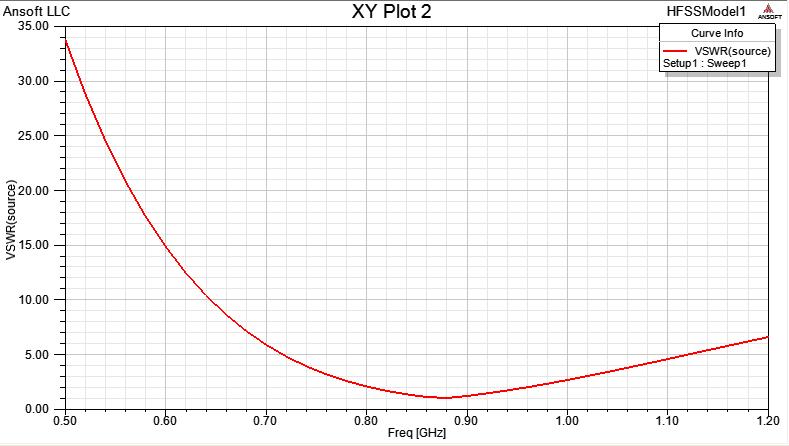
I am newbie to antennas and HFSS. I tried to simulate a thin dipole antenna whose resonant frequency is 865 MHz.

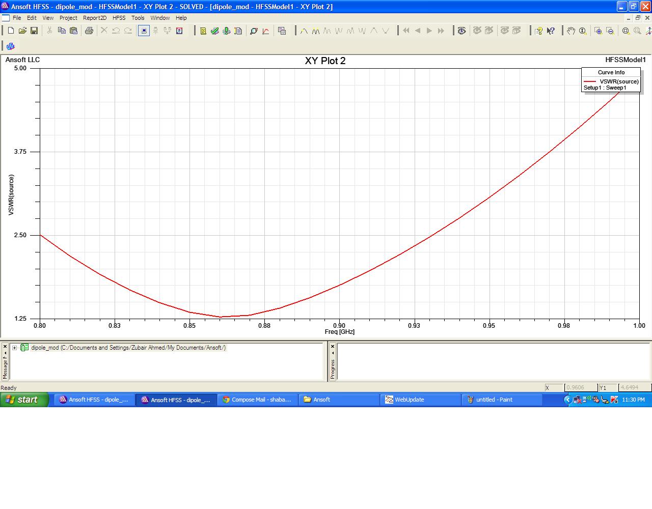
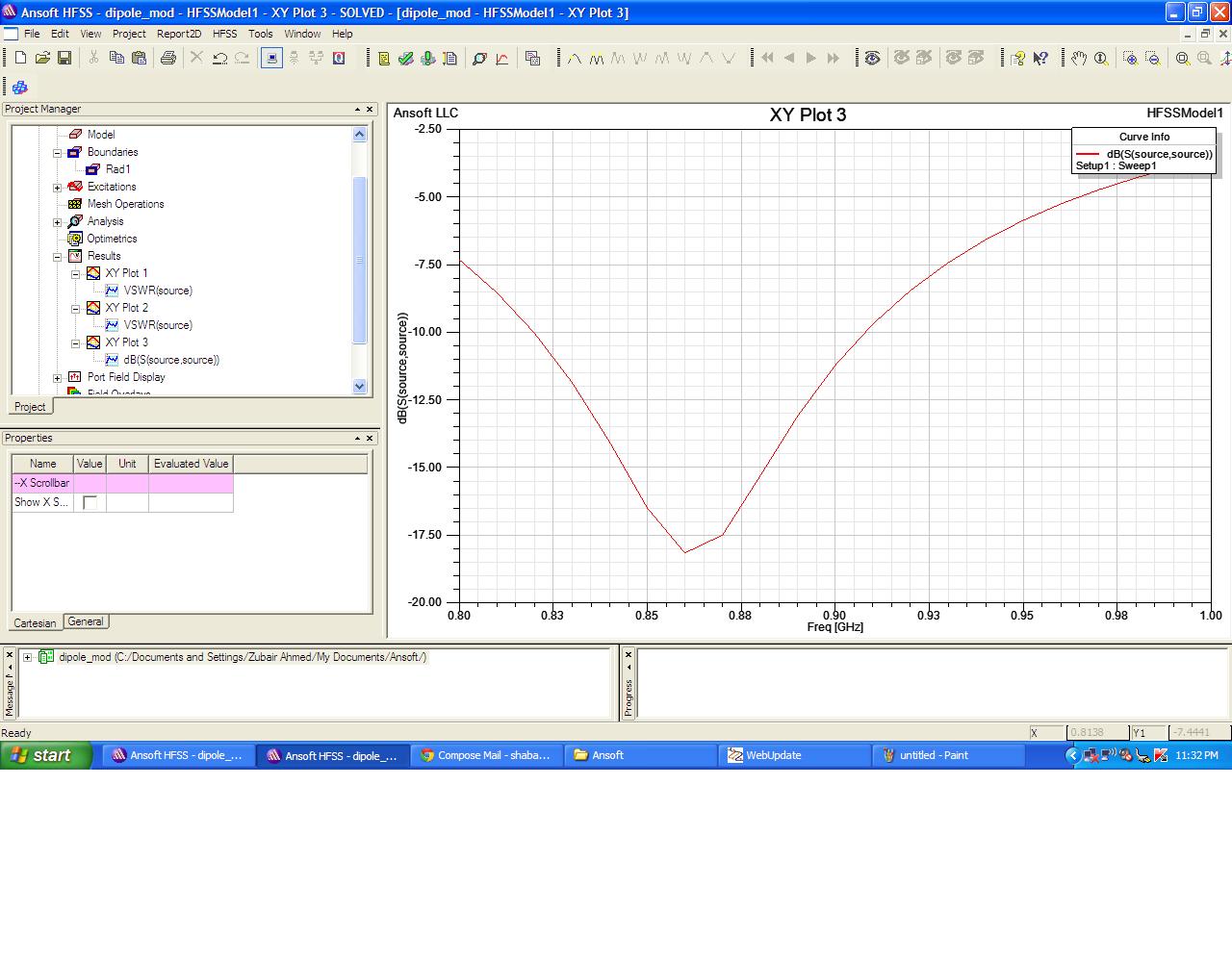
I simulated the results and found that VSWR is > 10. whereas ideally it should be less than 2.

What might have gone wrong? What should be the precautions to be taken care while designing the antenna to make sure that VSWR is < 2?

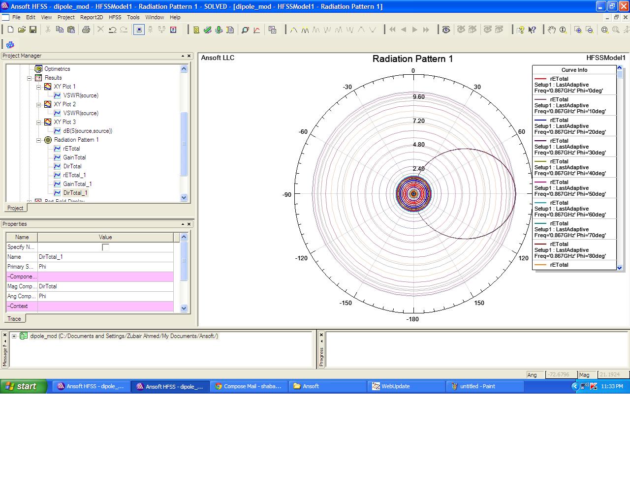
Whenever we measure radiation pattern, what should be the primary sweep (Whether it should be theta or Phi or frequency)?

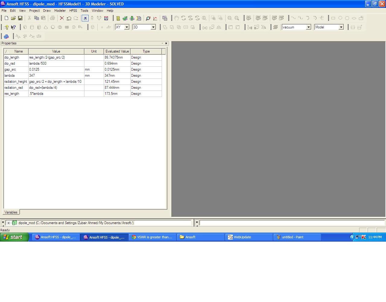
I have attached the .hfss file for reference. Let me know how I should make the design correct with good results?

Please help me out.

Thanks!
 

Attachments

  • dipole_mod.zip
    124.4 KB · Views: 108

Hi Shaikss,

for people (like me) that can't open hfss files, could you post drawings/plots of the antenna design?
Regards

Z
 

Hi Shaikss,

for people (like me) that can't open hfss files, could you post drawings/plots of the antenna design?
Regards

Z

I have followed the steps as per the below link

HFSS Tutorial

Guess this link gives you idea about the design.

Thanks
 

If you have really followed the steps.then i would say the only way you are not getting a perfect vswr if you not got your units properly. thats the only way i can see it.

Regards
 

If you have really followed the steps.then i would say the only way you are not getting a perfect vswr if you not got your units properly. thats the only way i can see it.

Regards

Units???
I have given the units all in mm. I am not sure what you are talking about.

Thanks!
 

Shaik i've figured out the problem with your design it was merely the rectangle that was used as a feed was way too small.i was wrong about it ,when i looked back,i meant feed of the rectnalge should be lambda/10 and not 100.Hope that helps

Now you will see a good resonance at your frequency

Regards

I will try to implement these changes and see how it goes. But I am very thankful to you. You have suggested and helped me a lot.
Thanks once again.
 

I will try to implement these changes and see how it goes. But I am very thankful to you. You have suggested and helped me a lot.
Thanks once again.

shaikss,

With just a little adjustment of some modeling parameters and increasing the gap a little, I managed to get this result:


I also attached the modified hfss file.


Jim
 

Attachments

  • dipole_mod_2.zip
    23.7 KB · Views: 84

shaikss,

With just a little adjustment of some modeling parameters and increasing the gap a little, I managed to get this result:


I also attached the modified hfss file.


Jim

Jim,

I can see only the plot but not .hfss file.
Actually, I have changed the rectangle dimensions. I could see an improvement in VSWR but the resonant frequency is slightly shifted.
Now, I am seeing for the trade-off.
Can you please let me know what changes did you do?

Thanks!
 

Well shaik if you increase the size of the rectangle,it literally increases the size of the dipole changing the resonant length.so you will have to decrease the size of the dipole length to get the proper resonance.simple as that

Regards
 
Well shaik if you increase the size of the rectangle,it literally increases the size of the dipole changing the resonant length.so you will have to decrease the size of the dipole length to get the proper resonance.simple as that

Regards

Hey,

I decreased the rectangle dimensions, thinking that VSWR will decrease and resonating frequency shifts left. But surprisingly, resonant frequency has shifted towards right. I will change the dimensions by following some range and then check how is it actually working.

Thanks!
 

if you decrease the size of the rectnagle, length of the antenna decreases implying increasing in frequency and increase in the antenna size leads to decrease in frequency and vice versa.

Simple as that.

Regards
 

if you decrease the size of the rectnagle, length of the antenna decreases implying increasing in frequency and increase in the antenna size leads to decrease in frequency and vice versa.

Simple as that.

Regards

For that sake, I have increased the resonating length of the dipole. I guess the amount with which VSWR is decreasing is not in proportion with the antenna length. I still need to increase the dipole length.

In between, I have a doubt. Normally dipole antenna length is little less than half the wavelength. What happens if it is slightly greater than half the wavelength inorder to see a good VSWR? Is it a good design? Or the design should need additional changes?

Thanks!
 

slightly over half the wavelength gives you impedance values above the desired Dipole impedance and the dipole acts more like an inductor.so its always important to have ti resonating at the right frequency.vswr will not remain the same and shift proportionally,because there are two changes that are happening with change in the length of the antenna.
1.change in the characteristic impedance
this change is triggering changes in the vswr and resonance.

hope that is helpful.These are basic facts that you can get yourself acquainted with by refering to a good text book. it will make your life lot easier in the future as well

regards
 

Well shaik if you increase the size of the rectangle,it literally increases the size of the dipole changing the resonant length.so you will have to decrease the size of the dipole length to get the proper resonance.simple as that

Regards

chachitoelflaquito,

Looking on the menu bar HFSS => "Design Properties" for parameter "dip_length" the definition is:

dip_length = res_length/2-(gap_src/2)

so it looks like parameter "gap_src" (*1/2) is subtracted from "res_length" (*1/2) to give dipole arm length. Also, res_length is defined as:

res_length = .475*lambda

or about 1/2 Lamda (.475 instead of .500 though).


Maybe the capacitance of the gap is used by HFSS in determining the antenna resonance? Or just maybe the change in dipole arm proximities? (as this affects the capacitance seen between the arms too.)


BTW, chachitoelflaquito, can you see if I attached the file: "dipole_mod_2.zip" (23.7 KB) correctly above (I am newbie to doing this on the board!)

Thanks for your input too.

Jim
 

So yeah

yes your file is uploaded properly.

Thanks a lot as well.
 

For that sake, I have increased the resonating length of the dipole. I guess the amount with which VSWR is decreasing is not in proportion with the antenna length. I still need to increase the dipole length.

In between, I have a doubt. Normally dipole antenna length is little less than half the wavelength. What happens if it is slightly greater than half the wavelength inorder to see a good VSWR? Is it a good design? Or the design should need additional changes?

Thanks!

shaikss,

A 'Normal' dipole in free space exhibits impedance at resonance of 72 to 73 Ohms (so say the text books on the subject) ... so VSWR will never be 'perfect' if referenced or 'measured' in a 50 Ohm system ....

Having said the above, I just noticed in the HFSS "Project Tree", under "Excitations" => source => "Properties" that it shows "79" Ohms in the window for "Full Port Impedance" (for what ever this is worth!)

I have much to learn about HFSS so I cannot offer any more guidance or advice on this, we need input from veterans and experts on this.

Jim

JIM

yes generally speaking when the dipole resonates, you get a characteristic impedance of close to 72 ohms plus reactive impedance of around 34 ohms as well. so when we check the resonance we are also concerned about the characterisitic impedance of the dipole. and if you don't normalize your impedance in the excitation, you should be able to see a appropriate results irrespective of the impedances you have entered in the boxes.

Regards
 

shaikss,

A 'Normal' dipole in free space exhibits impedance at resonance of 72 to 73 Ohms (so say the text books on the subject) ... so VSWR will never be 'perfect' if referenced or 'measured' in a 50 Ohm system ....

Having said the above, I just noticed in the HFSS "Project Tree", under "Excitations" => source => "Properties" that it shows "79" Ohms in the window for "Full Port Impedance" (for what ever this is worth!)

I have much to learn about HFSS so I cannot offer any more guidance or advice on this, we need input from veterans and experts on this.

Jim

Well said chachitoelflaquito.

I have modified the design properties in this manner:
I have attached the design properties which I have changed and the snapshots of VSWR, S11 and radiation pattern.


While drawing radiation pattern, which is the best method to consider primary sweep? Because when the primary sweep is varied (theta/phi/Freq), inference from plot also varies which is most obvious. But when you consider a design, what should be the best approach?

What is the best methodology to monitor characterstic impedence?

But I am grateful to you as you have clarified all my queries with lot of patience.

Please clarify this.

Thanks to Jim too :)
 

characterisitic impedance can be plotted using the same modal values,but this time you will be choosing z-parameters and then you plot IM and Re values of the Z-parameters.

Another point why do we not have half wavelength dipole rather than something less than half a wavelength. at half wavelength we see some reactance as well,inorder to minimize the reactance to zero we use a value less than that of the actual half wavelegth.

small tip,actually two
use more number of points in the sweep, you will see a smoothly curved plots

radiation patterns.i see you have an habit of having a scale of 0 to 180 in phi. its a good practice to have a scale of 0 to 360 degrees in both theta and phi plane. you will all the lobes minor major and side. and the step value make it 1 as well in radiation pattern for smoother curves.

Regards
 
Status
Not open for further replies.

Part and Inventory Search

Welcome to EDABoard.com

Sponsor

Back
Top