Continue to Site

Welcome to EDAboard.com

Welcome to our site! EDAboard.com is an international Electronics Discussion Forum focused on EDA software, circuits, schematics, books, theory, papers, asic, pld, 8051, DSP, Network, RF, Analog Design, PCB, Service Manuals... and a whole lot more! To participate you need to register. Registration is free. Click here to register now.

Combining RF signals to SSPA

Status
Not open for further replies.

Kaits

Junior Member level 1
Joined
Sep 14, 2009
Messages
18
Helped
1
Reputation
2
Reaction score
1
Trophy points
1,283
Location
South Pacific
Activity points
1,412
Hi Everyone
Can someone please help me with on how to connect more than 1 RF upconverter to a single SSPA as i've already tried connecting 2 upconverters using a combiner but what happens is that the carriers for 1 upconverter is running normally while the carriers on the other upconverter keeps turning on and off...Is it something to do with unbalance RF power input to the SSPA? Please if anyone can help or knows the solution i would really appreciate that.
Thanks in advance.
 

If you use a combiner, there should be no "interrupting" as you describe. Try to connect the "interrupting" input to the "healthy" input of your combiner, and/or test the suspected source separately.

Without more details, it is difficult to offer an advice.
 

If you use a combiner, there should be no "interrupting" as you describe. Try to connect the "interrupting" input to the "healthy" input of your combiner, and/or test the suspected source separately.

Without more details, it is difficult to offer an advice.


Hello jiripolivka
I've already tested each by connecting and testing one at the time of the Upconverters to the SSPA and each one worked normally but when combined only carriers from one works normally, the other keeps turning on and off..I even tried exchanging the combiner inputs for the 2 upconverters but still the same.

By the way For more details..
Im using an outdoor 40W transciever (HUGHES NETWORK SYSTEMS RFT-500)where HPA,Upconverter and Downconverter all in one casing but with output/input connection to each, and what im doing is tapping an external upconverter using a combiner to the HPA of the Transciever combining with the transceiver's own upconverter.
 

From the details you wrote I think the problem may be in the final-stage mismatch protector in one of the signal sources.
Please try to insert 3-dB attenuator pads into each of the inputs, and try to connect a termination instead of the antenna.

High-power signal sources (transmitters) often use an automatic switch-off for a mismatched load. One may be more sensitive than the other, or your coupler has a poor isolation.

In any case, attenuating the inputs may show if it helps, otherwise I would try another power combiner before SSPA.
 
  • Like
Reactions: Kaits

    Kaits

    Points: 2
    Helpful Answer Positive Rating
From the details you wrote I think the problem may be in the final-stage mismatch protector in one of the signal sources.
Please try to insert 3-dB attenuator pads into each of the inputs, and try to connect a termination instead of the antenna.

High-power signal sources (transmitters) often use an automatic switch-off for a mismatched load. One may be more sensitive than the other, or your coupler has a poor isolation.

In any case, attenuating the inputs may show if it helps, otherwise I would try another power combiner before SSPA.

I've tried attenuating the inputs and it improves but i cant attenuate further as the carrier then goes off as the tx power is too low.Is there anyway around this?
 

If adding an attenuator helps, it indicates to me that the load (the coupler or combiner) reflects back enough power to trigger the mismatch-protection circuit in the signal source.

If you can, try to use another power combiner, or, find by a reflectometer (or SWR meter) why the mismatch occurs and correct it. RF power sources like yours need such protection as by the reflected power the final stage could overheat and be damaged.
Another solution may be using a ferrite isolator if available for your frequency and power level. Its internal termination must be rated to absorb the reflected power without overheating.
 

Did the both upconverters using with same freq oscillator (TCXO etc)
if not please syncrosize them...

If I understand your problem correctly u connect two "different" signals into the combiner by different I mean they dont have same phase...


David
 

Did the both upconverters using with same freq oscillator (TCXO etc)
if not please syncrosize them...

If I understand your problem correctly u connect two "different" signals into the combiner by different I mean they dont have same phase...


David

Hello David
The two upconverters are using different center frequencies, I combined them using a combiner but I don't know if phase have anything to do with it, so can you please elaborate more on that as Im quite new with this, but as jiripolivka mention on past thread and have tried attenuating the signals and it really improves the outcome.. But please if its something with the phase can you please advice on how to go about resolving it.
Thanks
 
  • Like
Reactions: gulson

    gulson

    Points: 2
    Helpful Answer Positive Rating
Hi

Lets do example take u Power combiner and 2 different Signal generator
Define both of them (Signal gen) same freq and same power 0 dBm for example and 1GHz

Connect both signal to input of the combiner and sum port to Spectrum analyzer...

The results that u will see that signal will jump from 3 dBm to -3dBm (or something...) But u for sure will not get 3dBm const...
Splitter and Combiner it not the same "animal"...

U have the same problem at u system is not synchronized...

David

Can u please provide me some solutions so that I can try it out.

---------- Post added at 03:32 ---------- Previous post was at 03:17 ----------

If adding an attenuator helps, it indicates to me that the load (the coupler or combiner) reflects back enough power to trigger the mismatch-protection circuit in the signal source.

If you can, try to use another power combiner, or, find by a reflectometer (or SWR meter) why the mismatch occurs and correct it. RF power sources like yours need such protection as by the reflected power the final stage could overheat and be damaged.
Another solution may be using a ferrite isolator if available for your frequency and power level. Its internal termination must be rated to absorb the reflected power without overheating.

I've tried using the isolators, it improves somehow but no yet solve everything..by the way the BER readings for this carrier is abit high and is not stable what u think the main cause?? Is it still related to the reflected signal from the transmission? or from recieving signal
 

Try to take fundamental freq from one of the upconverters and inject it to the other as fundamental (disable the internal one and the second unit)
and than retest...

David
 

Try to take fundamental freq from one of the upconverters and inject it to the other as fundamental (disable the internal one and the second unit)
and than retest...

David

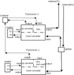
Can u please more details as I don't really get what u mean... by the way, here is a diagram of my set up.. Diagram1.jpeg

The modem connected to Transceiver 2 works normally and the modem connected to Transceiver 2 usually turns on and off..
 

Can u please more details as I don't really get what u mean... by the way, here is a diagram of my set up..View attachment 67601

The modem connected to Transceiver 2 works normally and the modem connected to Transceiver 2 usually turns on and off..
Sorry I mean The modem connected to Transceiver 1 usually the carriers goes off and on when combined with Transceiver 2, modem connected to Transceiver 2 function normally. But when decreasing down converter attenuation for Transceiver 1 somehow it affects the modem connected to Transceiver 2 meaning that the modems connected to Transceiver 2 alarms.
 

Now, having seen your schematic of actual connections, I want to ask: Why don't you use the power combiner AFTER both HPAs? Something in your connection is affecting one of both carriers from the two modems, but as you wrote, you saw some improvement if you attenuated one or both inputs to the one HPA. It again indicates for me that there may be some protection circuit, in the HPA or in the modem, which triggers reducing carrier power.
As you have two complete transceivers and use another power splitter (or combiner) in the lines from antenna to the two receivers, why not try to use the power combiner AFTER the two HPAs, to one antenna?

Satellite transceivers often have protection circuits that limit the carrier maximum power, watch for a mismatch at the RF output, etc. Maybe it is time to read the manual....
 

Can u please more details as I don't really get what u mean... by the way, here is a diagram of my set up..View attachment 67601

The modem connected to Transceiver 2 works normally and the modem connected to Transceiver 2 usually turns on and off..


Hi

According to u schematic
U inject from two different modems to two different upconvetrers...
and then u taking it to amp thru combiner...

Once again I am pretty sure that u problem that fundamental of both modems are not syncronized...

David
 

Hi

According to u schematic
U inject from two different modems to two different upconvetrers...
and then u taking it to amp thru combiner...

Once again I am pretty sure that u problem that fundamental of both modems are not syncronized...

David
Please can you advice solutions as how I can syncronize the two upconverters.
 

Now, having seen your schematic of actual connections, I want to ask: Why don't you use the power combiner AFTER both HPAs? Something in your connection is affecting one of both carriers from the two modems, but as you wrote, you saw some improvement if you attenuated one or both inputs to the one HPA. It again indicates for me that there may be some protection circuit, in the HPA or in the modem, which triggers reducing carrier power.
As you have two complete transceivers and use another power splitter (or combiner) in the lines from antenna to the two receivers, why not try to use the power combiner AFTER the two HPAs, to one antenna?

Satellite transceivers often have protection circuits that limit the carrier maximum power, watch for a mismatch at the RF output, etc. Maybe it is time to read the manual....
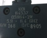
Can u please see this combiner (as attached)IMG0045A.jpg
if you think it can be used as power combiner as we dont have the specifications especially the power ratings for it and already tried searching in the web but cant find it..cos we already want to do that on first place but we fear that any mismatch or and problem from there would be more critical compared to combining first at the upconverters. Please advice as what should I do.
 

Status
Not open for further replies.

Part and Inventory Search

Welcome to EDABoard.com

Sponsor

Back
Top