Continue to Site

Welcome to EDAboard.com

Welcome to our site! EDAboard.com is an international Electronics Discussion Forum focused on EDA software, circuits, schematics, books, theory, papers, asic, pld, 8051, DSP, Network, RF, Analog Design, PCB, Service Manuals... and a whole lot more! To participate you need to register. Registration is free. Click here to register now.

understanding a relay

Status
Not open for further replies.

poxkix

Member level 5
Joined
Aug 20, 2011
Messages
87
Helped
0
Reputation
0
Reaction score
0
Trophy points
1,286
Activity points
1,948
Checked the suggested threads but I still need more explanation.

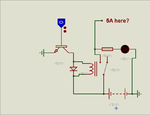
I have a 5A 12v relay. What does this 5amps mean, the amps needed to switch the relay on or it is an output related value from the relay?
 

Dear Friend
Hi
No . it just mean that your relay can support 5 amperes at the out put contact . and your input current will given by : 12v/DC impedance of it's coil .( if that is DC)
Best Wishes
Goldsmith
 
do goldsmith mean that the relay can support 5 Amps of load at its output ?

and the 12 V DC is the coil voltage ???

thanks
 

How to understand relay data.....

ex. relay is...Data sheet :Single-pole 10-A Power Relay

Relay_RelayData.jpg
 
Hello Kak111,
The datasheet shows that the coil is to be operated on 12v dc taking 33.3 mA current while the contacts can bear 8 A dc and 10 A ac.Regards
 
The 12 volt relay will only operate on dc and its contacts can be used for ac as well as for dc keeping in view the rated current.Regards
 

Dear ch wazir
Hi
I don't agree with you. you can find many 12 volt relays that can work at AC voltages ( their coil . ) . some of them are DC.
Regards
 

Dear Friend
Hi
No . it just mean that your relay can support 5 amperes at the out put contact . and your input current will given by : 12v/DC impedance of it's coil .( if that is DC)
Best Wishes
Goldsmith

Sorry so confused here.
I attached a file. Where did that 5A came from?
I thought 5A is max amps required to activate the relay coming from the input where the transistor is.

EDIT:
It is in DC voltage
 

Attachments

  • qwe.png
    qwe.png
    18.5 KB · Views: 109

Sorry so confused here.
I attached a file. Where did that 5A came from?
I thought 5A is max amps required to activate the relay coming from the input where the transistor is.
qwe-Rotated-Named.png
In order to avoid confusion I have rotated the file, named the parts and A brief explanation is given below.
First, the abrrevated terms
T1= Transistor 1 (npn)
NC= Normally Closed Point
NO = Normally Open Point
Common pnt = Common Point
GND = Ground

Hope that clears the first part...... Now look in the schematic I reattached . It is time for us to know a bit about working

Our relay is activated. when the current is passed through the relay coil.. Now again have a look in the schematic. Here the positive voltage applied to the base of the T1 (since NPN) will helps to create the path for the current to pass through the coil and activate the relay. Note since the other end of the relay is connected to the battery array, the current flows from the positve terminal of the battery, through relay coil, then to the transistor T1 and then to ground. (have a look in the schematic to have a proper understanding).. If you understood up to this point, then continue reading. Otherwise understand it first....

Thus the current flows through the relay coil when T1 is ON.. This will magnetize the relay coil and causes the common point connector (the rod is attracted) to move from normally closed point to normally open point.Understood?

Now we connected 5A to the Normally Open point and now it is connected to the coomon point. thus 5A is reaching th common point. Now look, according to your schematic, the common point is again connected to the battery array..( I can't explain why it is connected so.Because you didn't mention the purpose of this circuit anywhere). Now the 5A (either ac/dc -since you didn't mentioned it) will be reaching that point.

(note this circuit may be used for battery charging controlled by another source through the port pin).

Ok.that doesn't matter in the understanding of relay....... Now you understood that when the relay is activated, the connection from the normally closed point will be shifted to normally open point (the reverse is occured when the relay is deactivated). thus the electrical connections can be made b/w common point and NC or Common point and NO. Higher amplitudes of voltages (or current, both depend on max rating) can be given in NC, NO or Common Point. and the common point connections can be controlled by a small current(voltages, as done by enabling T1)....... Thus high voltages ( Current) can be controlled by smaller ones...........

Go through the schematic again to grasp the concept........ Now about the ac or dc requirements..... what we need is to do the switching. for that we need to magnetize the relay..... this can be done by using ac or dc....... (depending on the coil types)...

Now these explanations hopfully enough to clear your doubts....
Now read your question
Where did that 5A came from?
I thought 5A is max amps required to activate the relay coming from the input where the transistor is.

Try to find out the answer yourself (recommended).....

Or read below.
question 1
Where did that 5A came from?
Ans: it is given from an external circuit

Question 2
I thought 5A is max amps required to activate the relay coming from the input where the transistor is
the answer maybe pretty much clear now.......
Ans: No. the input from the port is deciding the turning on and Off of relay......... the 5A is the signal that is required to switch using relay through the common point..

Hope that you found this helpful............
in case of any doubt...please be free to post
all the best from RJK
 
View attachment 67280
Our relay is activated. when the current is passed through the relay coil.. Now again have a look in the schematic. Here the positive voltage applied to the base of the T1 (since NPN) will helps to create the path for the current to pass through the coil and activate the relay. Note since the other end of the relay is connected to the battery array, the current flows from the positve terminal of the battery, through relay coil, then to the transistor T1 and then to ground. (have a look in the schematic to have a proper understanding).. If you understood up to this point, then continue reading. Otherwise understand it first....

Yes, I have understood this part.
So a relay is activated by a given current. How do I determine the minimum required current for a 5A 12v relay to activate? given that 12v DC is the given voltage.
I searched and is the V = IR the right solution? Or as we say the Ohm's Law.


Now we connected 5A to the Normally Open point and now it is connected to the coomon point. thus 5A is reaching th common point. Now look, according to your schematic, the common point is again connected to the battery array..( I can't explain why it is connected so.Because you didn't mention the purpose of this circuit anywhere). Now the 5A (either ac/dc -since you didn't mentioned it) will be reaching that point.
(note this circuit may be used for battery charging controlled by another source through the port pin).

Okay so 5A is the max value given by an external circuit?
It is DC, I think I mentioned it a while back.
Currently I'm using this to control a coin slot to power it on or off. At first I didn't mind what values the relay have as long as it is 12v not until I was questioned why I chose a 5A 12v DC relay and it started all of my confusions.

I will also use this setup to control a battery charger.
 

The word RELAY means to receive from one and to send to another. Exactly same the electronic relay means, it receives from one circuit and sends to to another. This is in two parts, ONE is the operating coil which is energized when electrical voltage is supplied to it and causes to attract the IRONIC objects be attracted to the central IRON piece of the coil. Here is a good explanation of a relay's work of actual relay.
Relays
Any relay can work on AC or DC, BUT the problem on AC operation of the coil is that the Magnet POLE (inside the coil) needs to neutralize the EDDY currents produced by AC inside it. So what we do in AC coils we put the IRON lamination to overcome this problem other wise the PLUNGER being attracted to the magnet will vibrate on 50 or 60 Hz.
Here is very good animation of relay circuit.
HowStuffWorks "How Relays Work"
In the following attached circuit (from post # 11 and 12)
Relay.JPG
The Diode in Red boundary is connected in wrong direction as it is in forward bias connection and as soon as the Relay Contact is closed the diode will conduct in parallel to the relay contact and will provide additional load to the battery for nothing. Abbreviations are as follows:
NC = Normally Closed Contact
NO = Normally Open Contact
COM = Common Contact
There are two things are mentioned normally for a relay,
1. The coil operating voltage + current (some times)
2. The Contact current which can be switched for maximum.

Thank you for the links.
So I will just reverse the diode to make it right? right?
 

yes, But why you need this Diode in the circuit ?. It has no function apparently or please post the final circuit for further guidance.
 
Dear Raza
Hi
What do you mean by" But why you need this Diode in the circuit ?. It has no function apparently or please post the final circuit for further guidance." ?
That is fly back diode ( freewheeling diode ) . if you prevent to use that diode in parallel with your relay , when your transistor is on , we don't have any problem . but when the transistor , wants to be turn off , according to the lenz law (E=L*di/dt) , the inductor of the relay , try to increase the voltage , up to hundreds of volt( at the reverse polarity) . thus that diode can does short circuiting that inductor opposition.and thus can keep your transistor.
Best Wishes
Goldsmith
 

Raza giving some false information?
 

Yes, I have understood this part.
So a relay is activated by a given current. How do I determine the minimum required current for a 5A 12v relay to activate? given that 12v DC is the given voltage.
I searched and is the V = IR the right solution? Or as we say the Ohm's Law.

question 1

So a relay is activated by a given current
Actually Yes, But since the current sources are not readily available, we use the voltage sources........ The rating 12v 5A means the switching is occured at 12V
and it can carry 5A of current safely........

Question 2
How do I determine the minimum required current for a 5A 12v relay to activate? given that 12v DC is the given voltage.
I searched and is the V = IR the right solution? Or as we say the Ohm's Law.

Actually it is ohms law, but instead of R (resistance) you have to use Impedance(z= R+jX where X is the inductive reactance) of the relay coil to calculate the current flows through it.


Currently I'm using this to control a coin slot to power it on or off. At first I didn't mind what values the relay have as long as it is 12v not until I was questioned why I chose a 5A 12v DC relay and it started all of my confusions.

As I mentioned in section below in Post #12
Thus the current flows through the relay coil when T1 is ON......... Now look, according to your schematic, the common point is again connected to the battery array..

The input you connected to your normally open point will be reaching the common point when relay is activated....... so if your coin box requires some voltage when the relay is activated, you have to connect the required voltage in NO, provided your coin box doesn't require a current more than 5A @ that particular voltage. Also you have to change the connection from "Common point to battery" to "common point to Coin box power input"....... So when the relay activated the power will be reaching the coin box........... (Note: if your coin box require a current greater than 5A you have to change the relay to a higher current rating. If that much is not needed you can go for lower current rating (reduced price) or you can keep this itself.)

An schematic bellow will show you the connections...... for better understanding.......
note dashed lines are the changed connections
qwe-RN-New.png
thus the required voltage will reach the relay when power on

Question 3
So I will just reverse the diode to make it right? right?
This is as I mentioned is flyback or free wheeling diode) Gold smith on post #17 gave why it is connected so........

(Edit: If you want you can connect without flyback diode..... thi circuit will work for the first time. but when you again give the signal to relay, it will cause problems... some times may destroys entire circuit)
Hope this clears all your doubts.........
 
Last edited:

Status
Not open for further replies.

Similar threads

Part and Inventory Search

Welcome to EDABoard.com

Sponsor

Back
Top