Continue to Site

Welcome to EDAboard.com

Welcome to our site! EDAboard.com is an international Electronics Discussion Forum focused on EDA software, circuits, schematics, books, theory, papers, asic, pld, 8051, DSP, Network, RF, Analog Design, PCB, Service Manuals... and a whole lot more! To participate you need to register. Registration is free. Click here to register now.

Why do they use diodes 4148 in this circuit

Status
Not open for further replies.

ze-trinchas

Newbie level 6
Joined
Jul 4, 2006
Messages
13
Helped
0
Reputation
0
Reaction score
0
Trophy points
1,281
Activity points
1,377
Hi,

I have a question.

Can anyone explain me the reason they use the 4148 diodes in this circuit, both in the relay coil and in the input control circuit?

**broken link removed**

Best regards?
 

When a relay is de-energized, the collapsing magnetic field generates a transient across the coil that could cause some mischief. The diode is there to short out any reverse-current spikes.

Personally, I've never found it necessary to include such a diode when the coil is energized with a transistor, as it is here. It is vitally important, though, if a switch or another set of relay contacts energizes the coil.
 
A relay coil is an inductor. When the current in an inductor is suddenly turned off, it induces a high voltage spike that may be harmful to some components or cause interference. For example, the turn-off spike across a 12V relay coil may be higher than 100V. It might even cause a spark across the relay coil windings. The diode across the relay coil absorbs that voltage spike.

The polarity of the spike is opposite to the polarity of the original voltage across tha inductor. So, if we place a diode across the inductor with its polarity opposite to the normal relay coil voltage, the diode is reverse-biased and does not pass any current when the relay is activated. When the relay is turned off, the voltage spike is in the opposite polarity and the diode now conducts, thus reducing the spike to the forward diode drop of less than 1V.

Regarding D4 and D5 across the inputs, they also act to shunt any reverse voltage across the red LEDs and the optocoupler inputs. As the document is incomplete and does not show what kind of input is expected, it's not clear why they need to be there. If the input is only a clean positive digital pulse, D4 and D5 are not needed.
 

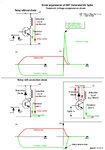
Diode suppression of EMF Generated HV Spike
Transient-voltage-suppression diode

When an electromechanical relay is de-energized rapidly by a mecanical
switch or semiconductor, the collapsing magnetic field produces a
substantial voltage transient in its effort to disperse the stored energy
and oppose the sudden change of current flow.
A 12VDC relay, for example,may generate a voltage of 1,000 to 1,500 volts
during turn-off.
The protection diode connected across the relay coil ( inductor) is normally reverse biased,
as the voltage on its cathode, connected to the +V supply rail, will be more positive
than its anode on the collector of the transistor. At switch off however, a large voltage
spike of opposite polarity appears across the inductor, due to the collapsing magnetic field.
For the duration of this voltage spike, the collector of the transistor could be at a higher
potential than the supply, except that if this happens, the diode will become forward biased
and prevent the collector voltage rising any higher than the supply rail.

Supression_Diode_01.jpg
 

The answers given to your question are correct. However, a note of caution is in order. The suppression diode causes the relay coil currrent to decrease exponentially with a time constant of L/R where L is the relay coil inductance, and R is the relay coil resistance. This slow decay of coil current causes the relay contacts to open slowly. This can cause excessive arcing, and reduced contact life. This is normally a problem when the relay contacts handle large currents and/or inductive loads. One way to avoid this problem is to connect a zener diode in series with the suppression dide. This allows that induced voltage across the coil to rise to a value sufficient to reduce the contact actuation time. A Zener voltage of approximately twice the coil voltage rating generally produces good results.
 

Status
Not open for further replies.

Similar threads

Part and Inventory Search

Welcome to EDABoard.com

Sponsor

Back
Top