Continue to Site

Welcome to EDAboard.com

Welcome to our site! EDAboard.com is an international Electronics Discussion Forum focused on EDA software, circuits, schematics, books, theory, papers, asic, pld, 8051, DSP, Network, RF, Analog Design, PCB, Service Manuals... and a whole lot more! To participate you need to register. Registration is free. Click here to register now.

[SOLVED] Wireless Power Transfer

Status
Not open for further replies.

CataM

Advanced Member level 4
Joined
Dec 23, 2015
Messages
1,275
Helped
314
Reputation
628
Reaction score
312
Trophy points
83
Location
Madrid, Spain
Activity points
8,409
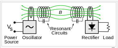
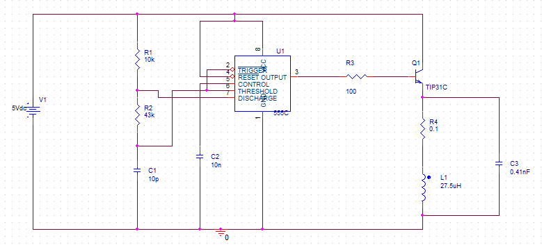
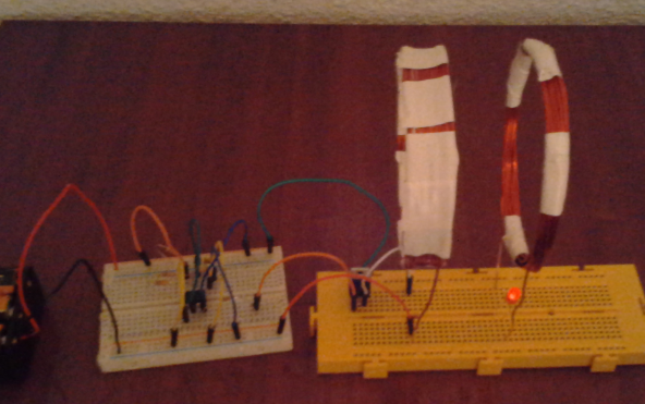
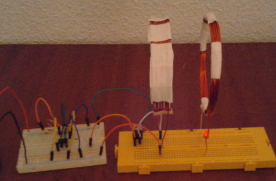
I am trying to build a circuit that transfers electricity from a coil to an other (to the secondary due to Faraday's Law).
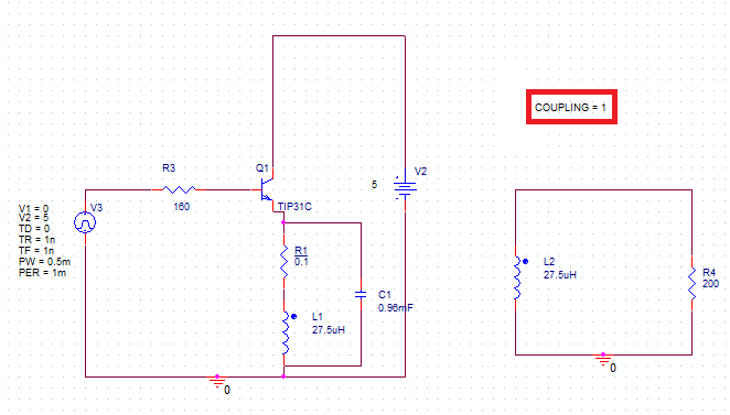
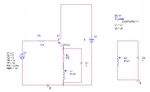
The circuit I built is the shown in the figure and I have 3 questions:


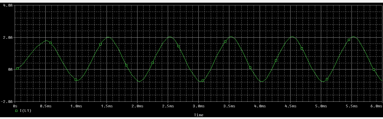
1) Is this going to work? I mean, how far I am going to be able to separate the second coil from the primary coil? The input voltage is provided by Arduino UNO...

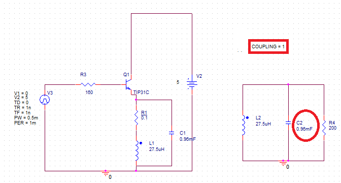
2) To hit the resonance, it is correctly placed the 2 capacitances "C1" and "C2" shown in the picture above?

3) To determine the 2 capacitances, it is correct the following formula to use?

\[C=\frac{1}{4{\pi}^{2}{f}^{2}L}\]
L=inductance of the solenoid, f=1 kHz (provided by arduino)
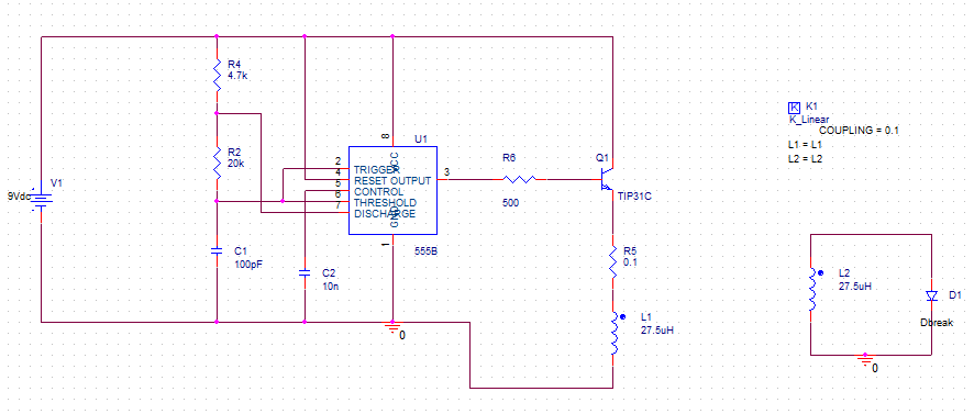
 

Attachments

  • 1.png
    1.png
    8.2 KB · Views: 104
Last edited:

Coupling gets weaker as coils are further apart. Similar to transformer coupling coefficient.

You might pick up some tips by looking at cordless chargers for toothbrushes and hearing aids. I don't think manufacturers will reveal secrets, however.

It becomes a question whether you need resonance in the transmitting circuit. You could simply drive the coil alone, with a sinewave, at a reasonable frequency. Your receiver ought to have the resonant LC arrangement. Tune whichever circuit is more convenient to tune.
 
  • Like
Reactions: CataM

    CataM

    Points: 2
    Helpful Answer Positive Rating
1) Brad's right, how far you can separate the coils will be determined by the size (typically diameter) of the coils, and how much power you really need to receive.

2) Typically a resonant circuit will result in higher power transfer efficiency (PTE), but like Brad pointed out its not required.

3) Yes that's correct for obtaining a resonant circuit. In your diagram, however, I don't see any load to deliver power to. Typically this is some rectifier circuitry, which could be a complex load. This could result in detuning of the resonant circuit.

Some impedance matching circuitry will also be needed to get truly optimal PTE, but if you plan on using "strongly coupled" coils (for me I'd call k > 0.5 strong), then you can probably ignore that. If you'd like to power across a decently large distance (say 2x the diameter of your coils) then I recommend reading into Magnetic Resonance Coupling (MRC), a fancy way saying optimal inductive charging.
 
  • Like
Reactions: CataM

    CataM

    Points: 2
    Helpful Answer Positive Rating
2) Typically a resonant circuit will result in higher power transfer efficiency (PTE), but like Brad pointed out its not required.

How to know if is required or not?

In your diagram, however, I don't see any load to deliver power to. Typically this is some rectifier circuitry, which could be a complex load. This could result in detuning of the resonant circuit.

As a load I can use an LED to see how far it is going. It is required the LC in the receiver circuit then?


My only goal is to separate the coils as far as the circuit allows me, so I need to make the best coupling possible, thats why I am asking for the resonance.
 

A Wikipedia article describes a resonant LC loop at both sending and receiving stations.

https://en.wikipedia.org/wiki/Wireless_power

Excerpt:

In 2007 a team led by Marin Soljačić at MIT used
two coupled tuned circuits each made of a 25 cm self-resonant
coil of wire at 10 MHz to achieve the transmission of 60 W of
power over a distance of 2 meters (6.6 ft) (8 times the coil
diameter) at around 40% efficiency.

2565550900_1450930142.png


Another article states that the shared resonance (as well as high Q), provides better coupling and better efficiency.

https://en.wikipedia.org/wiki/Resonant_inductive_coupling
 
  • Like
Reactions: CataM

    CataM

    Points: 2
    Helpful Answer Positive Rating
After adding capacitors in my circuit, I simulated it with Orcad and got some graphics that don't understand.

First circuit is adding just 1 capacitor in the transmitting circuit:


And the current through the first coil (L1) is the following:


But after adding the second capacitor in the receiver circuit, as figures in the next picture:


The current through L1 is like this (very distorsionated):


My question is why happened that?

NOTE: The coupling is assumed to be k=1 always.
 
Last edited by a moderator:

I believe your LC tank circuit (L1 & C1) resonates at a different frequency than your waveform generator. It generates a conflicting waveform.

Try removing C1.

Alternately, there are oscillating circuits which automatically detect the LC resonant frequency. That may be worth a try.
 
  • Like
Reactions: CataM

    CataM

    Points: 2
    Helpful Answer Positive Rating
First case is in resonance, second isn't.
 
  • Like
Reactions: CataM

    CataM

    Points: 2
    Helpful Answer Positive Rating
the second circuit has the same frequency as the first one..
Not at all. Setting K=1 makes the two inductors behave like one. Only separated by the 0.1 ohm resistor, both capacitors are effectively connected in parallel. First resonance circuit is 27.5 µH || 0.96 mF, second double the capacitance. Resonance frequency is altered respectively.

Of course K=1 isn't a reasonable model of your "wireless power transfer" problem. Choose K=0.1 or even lower.
 
  • Like
Reactions: CataM

    CataM

    Points: 2
    Helpful Answer Positive Rating
Hm, the mutual inductance will affect both inductors: Mutual_inductance_equivalent_circuit.svg.png

Where M is the mutual inductance between L1 and L2 and k = M/sqrt(L1*L2). Never dealt with strong coupling before. But wouldn't this detune both inudctors equally?
 

But wouldn't this detune both inudctors equally?
This is the current through the secondary coil with K=1. Seems to still be a sine wave with 1ms of period.


Of course K=1 isn't a reasonable model of your "wireless power transfer" problem. Choose K=0.1 or even lower.
Yes I know, but just saw that and was surprised.
 

Well at least that graph makes sense. For simulation purposes, it might be better to work in the frequency domain instead of the time domain until you deal with rectifiers. You could just use a 50 Ohm AC source for your Vin.

Do you already have coils made? If so, you'll want to know their inductance and Q factor at your operating frequency. Higher operating frequencies generally lead to higher Q until you hit the self-resonant frequency, at which point Q decreases. Larger coils have lower self-resonant frequencies, but if you're operating at 1 kHz you're far from that region.

Higher Q also leads to better power transfer as a function of distance. Larger coils couple better (larger k) and also generally have larger Q. Inductance is just important for establishing resonance.

If you know how much power you can source from your adrunio and how much power you need to be receiving, you have a target PTE. Now just determine what is the lowest possible k for which that PTE can be achieved for a given set of coils (Q and L).

The method Brad described in those Wikipedia links is a form of Magnetic Resonance Coupling. You'll notice it involves four coils and some analysis that's probably a lot of trouble for your project (but still very interesting!). The team he mentioned went on to found Witricity, a company looking to bring wireless power transfer into many more industries: **broken link removed**
Their whitepaper is a great summary on WPT and understanding how to get the most bang for your buck (PTE over distance). Really, MRC is just optimal wireless power transfer, and can be physically realized with giant helices or other (more compact) means.
 
  • Like
Reactions: CataM

    V

    Points: 2
    Helpful Answer Positive Rating

    CataM

    Points: 2
    Helpful Answer Positive Rating
I am a really newbie in this field and in electronics in general (maybe in other countries, in the university have a higher level, but in my country just telling you that this year we learned the frequency domain you can realise how low level I am... not saying that all this people answering questions is playing in another league). Maybe for you I am asking stupid questions...

Also I am aware that this is rubbish circuit and may not work. Watching other circuits and I am embarrassed, but thought that if I tune it well it could work to blink a LED far away at least 4 cm..
Also saw very good circuits but I don't know how to theoretically analyze them like this one on this page:
http://www.vk2zay.net/article/262

Also, as Brad said, and read in those articles, and you said, the frequency increases Q and so the distance, so I also thought about this circuit on 1.5 MHz with CMOS 555 (saw a thread on this forum and a guy said is working up to 3 MHz).


My goal initially was to get between 0 and 5 V on the secondary coil which is mission impossible for my circuit. So my goal now is just to blink an LED as far as I can from the TX circuit... more than 3 cm it would be great.
Also here is a good circuit which works up to 8 cm far away from the TX but I don't know how he tuned this Hartley Oscillator:
http://voltage.g6.cz/bezdratovy-prenos-energie.php

Didn't seem to be very difficult, I mean this guy achieved it, not very far but done:

Back to my work,I am planning to build 8 cm diameter coils with 1mm wire and 15 turns. I am calculating the "L" with this formula:
\[L=\frac{mu0 {N}^{ 2} A K }{ l}\]
K=Nagoaka coefficient
l=length of the solenoid
mu0=4*pi*10^(-7)
A=area of the cross section

How would you calculate it ? And Q, not even thought about it..

To have a big flux is needed a big current, that is why I am using so low resistances and 1 A I think it is sufficient.
 
Last edited by a moderator:

Don't worry about being new. Optimally efficient wireless power transfer is an active research area! I must admit, I'm not very helpful at analyzing oscillators either, sorry I can't offer any advice there.

For the coils, you could probably get away with just building those coils, getting a close enough approximation for L, put on some resonant caps for the frequency you want to operate at, and just see how far you can power an LED. This is the more tinkering approach, if you're doing this for a class you might want to do the quantification as well. Especially if you would like a simulation to match your physical results!

Nice, 8 cm coils should be plenty large enough to get strong coupling at only 4 cm apart. If you just wind some copper wire together you should get decent results. As far as measurements go, what sort of equipment do you have access to? Oscilloscope, arbitrary waveform generator, LCR meter? I would recommend making another measurement of inductance after building your coil to make sure you're in the ballpark if you can, the equations can be a little off which can make designing the caps for resonance tricky.

Q factor for an inductor is defined as Q = 2pi*f*L/Rs where Rs is the series resistance of the coil. You could measure the DC resistance using a multi-meter and hope it doesn't change too much for your operating frequency, more likely than not you'll have a high enough Q to ignore it in simulation. An LCR meter would be able to measure at the frequency you care about, that would be the best case scenario. You could also use that to measure inductance at your operating frequency.

To measure coupling there are a variety of methods for measuring mutual inductance, this one seems relatively painless: https://www.daycounter.com/LabBook/Mutual-Inductance.phtml
 
  • Like
Reactions: CataM

    CataM

    Points: 2
    Helpful Answer Positive Rating
As far as measurements go, what sort of equipment do you have access to? Oscilloscope, arbitrary waveform generator, LCR meter?
Nothing for now, that is why I am using the simulator so much, OrCAD became my brother nowadays :grin:

Of course my calculations are just to see around which magnitudes I am moving and of course a LCR meter to measure L would be the best in order to get closer and match resonance with the right capacitors...

The circuit with 1kHz simulated, even with coupling=0.1 get almost all the TX current into the Rx, and with k=0.001 got some mili amps (now I see what means the resonance), the problem is with the Q, because with Rs=0.1 ohm (calculated in DC) and low frequency don’t reach the Q=2.. awful. Of course who has the last word is real experimentation.

The other circuit with the 555 CMOS, even though it has 1.5 MHz freq, the inductance (27.5 uH) is high for that frequency and the current variates little (between 1A and 1.1 A) so gives worse results than the 1 kHz circuit, for example at k=0.1 in the Rx I got some few mA. Nevertheless, since the Q is higher, I think that "k" will be further reached from the TX.

To make a serious Wireless Power Transfer circuit is needed equipment, accurate measurement and a lot more theoretical study…
 

Finally made it and worked.. but not very far, a bit more than 4 cm away.

The Arduino circuit didn't work, I think because of the low frequency.

The circuit who worked is this one over here:


It isn't the CMOS 555 because couldn't find it, so I used the poor NE555 and also because of that unscheduled situation didn't had the capacitors to match it well. Theoretically frequency is more than 300 kHz but in the simulator gives 90 kHz, I don't know which one worked.
Also the BJT transistor got very hot, I think there was near 1 A.

Here are some pictures and hope some day make better calculations, better coils, better electronics, some capacitors, higher frequency, maybe more coils like the "wiricity" project etc..


In those pictures the LED lights up a little and the coils are separated 4 cm.

Also here is a demonstration video of my poor circuit.

https://www.dailymotion.com/video/x3k20ot_cto_tech

Thank all of you guys for answering my stupid questions and waste your time.
BradtheRad, kthackst, FvM
 
Last edited by a moderator:

Very positive. Sorry but the blank window did not display your video at the hosting site. My simple fix was to give the url. Your link was not necessarily broken, but evidently the 'sharing' function doesn't work with that site, as it does work with Youtube.
 

Status
Not open for further replies.

Part and Inventory Search

Welcome to EDABoard.com

Sponsor

Back
Top