Continue to Site

Welcome to EDAboard.com

Welcome to our site! EDAboard.com is an international Electronics Discussion Forum focused on EDA software, circuits, schematics, books, theory, papers, asic, pld, 8051, DSP, Network, RF, Analog Design, PCB, Service Manuals... and a whole lot more! To participate you need to register. Registration is free. Click here to register now.

Why we use Latch for Gated Clocks

Status
Not open for further replies.

spartanthewarrior

Full Member level 2
Joined
Jun 13, 2007
Messages
122
Helped
0
Reputation
0
Reaction score
0
Trophy points
1,296
Activity points
2,142
HI,

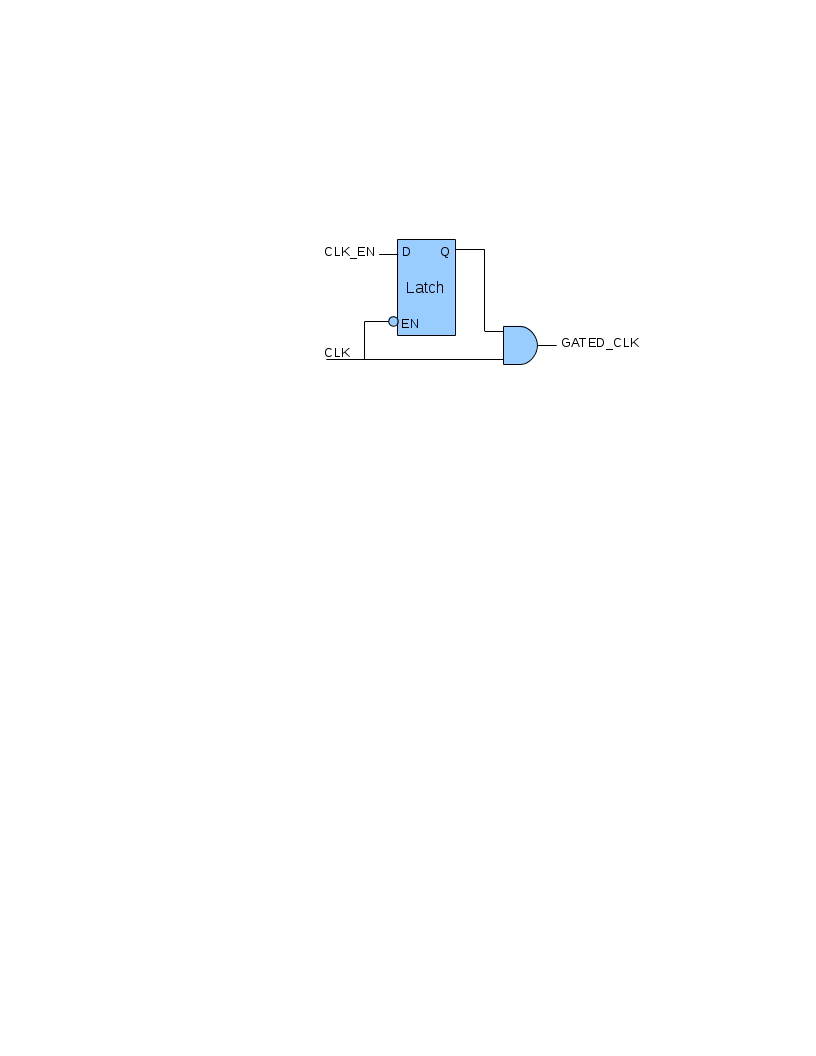
All can any tell me why we use latch for gated clocks even though we dont want latches in our design.
 

i think it can avoid the effects of the glitchs in the gated clock's region.if we don't use it , there may be a wrong when the clock works.That means you may get the wrong data in the time you don't want .
 

Hi,
ANDing clock with enable signal while clock gating requires that enable should be held high from acive clock edge to inactive to avoid any truncation of clock signal.

But when latch is used,latch takes above care to maintain full required clock.
 

You wrote: "latch takes above care to maintain full required clock" - could you give more detail explanation?
 

In clock gating using latch, we are still ANDing CLK with CLK_ENABLE signal, but not directly. As explained above, if we simply AND CLK_ENABLE and CLK, then in the actual design CLK_ENABLE may come from combinational path with varying delay which if deasserted during high cycle of CLK, then the output of AND will be clipped clock. This may cause problem in the design.

Now, using latch we can fix this issue. Simply feed CLK_ENABLE to the input to the latch, and feed the clock to the active low enable input of the latch. AND the output of the latch with clock.

The latch is transparent only when CLK is low, otherwise opaque. When CLK_ENABLE is low, the output of latch and AND gate is always low. This means clock is 'gated'. Now, what happens if CLK_ENABLE is high? the output of AND gate doesn't go high immediately because latch is opaque during high cycle of clock. Only when clock is low, CLK_ENABLE is pass through the latch the AND gate. When clock goes back to high cycle, since CLK_ENABLE is already asserted, there is no chance of clock clipping.

I hope this helps.
seriously it needs pictorial explanation.
could you please add some diagram here.
 

The clock gating logic block diagram can be easily found by using google or any digital design text book. Anyway, to make life easier, the diagram pertaining to above explanation is attached.
 
good job morris_mano.

We need contributing members like you.

+10 points for your visual contribution
 

Status
Not open for further replies.

Part and Inventory Search

Welcome to EDABoard.com

Sponsor

Back
Top