SanjKrish
Member level 3

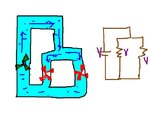
Comparing parallel voltages with the water analogy do u think the two loads separating from the main pipe will experience the same push on them...
if the water flow in the main pipe is now doubled then how does the generator double the water flow without increasing the push..
(how can the voltage source supply double the the current without increasing the voltage ?? since naturally more push by the generator only will give rise to more current flow through the pipe