Continue to Site

Welcome to EDAboard.com

Welcome to our site! EDAboard.com is an international Electronics Discussion Forum focused on EDA software, circuits, schematics, books, theory, papers, asic, pld, 8051, DSP, Network, RF, Analog Design, PCB, Service Manuals... and a whole lot more! To participate you need to register. Registration is free. Click here to register now.

why voltage is same across parallel resistors( another confusion)

Status
Not open for further replies.

SanjKrish

Member level 3
Member level 3
Joined
Feb 6, 2011
Messages
67
Helped
1
Reputation
2
Reaction score
1
Trophy points
1,288
Location
India
Activity points
1,855
parallel resistance.JPG

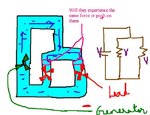
Comparing parallel voltages with the water analogy do u think the two loads separating from the main pipe will experience the same push on them...

if the water flow in the main pipe is now doubled then how does the generator double the water flow without increasing the push..
(how can the voltage source supply double the the current without increasing the voltage ?? since naturally more push by the generator only will give rise to more current flow through the pipe
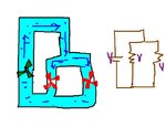
 

Attachments

  • parallel resistance.JPG
    parallel resistance.JPG
    32.7 KB · Views: 171

If both of the load are equal then the force experienced will be equal... Now match it with voltage across resistors...
 

The power supply voltage remain constant and exerce no push. It is the resistance who will draw the current from the source depending on their resistance value. The current max drawn will depend on the power of your source. You have to study power supply source to understand this analogy.
 

If a real circuit is formed with a voltage source and a resistor as a load, the load voltage decreases if we add, for example, another similar resistor in parallel to the original one. The more the internal resistance of the voltage source (pipe resistance) is, the more the voltage drop on the load is.

As you said, if we like keeping the load voltage constant, we have to find a way to compensate the voltage drop due to the internal resistance (pipe) by increasing the source voltage (pump).
 

View attachment 94662

Comparing parallel voltages with the water analogy do u think the two loads separating from the main pipe will experience the same push on them...

if the water flow in the main pipe is now doubled then how does the generator double the water flow without increasing the push..
(how can the voltage source supply double the the current without increasing the voltage ?? since naturally more push by the generator only will give rise to more current flow through the pipe

Two resistors in parallel have same voltage across them whether they have same resistance or not. This can be understood using water analogy as follows:
Consider a pipe with dimensions: length(l), cross-sectional area(area seen when we cut the pipe perpendicular to direction of water flow, just to remind;-)) as A. Now if we pass some amount of water from 1 end, it would require some time to come out from other end. Now, if we increase the length of the pipe to 2l, then for same amount of water we wold require double time. Similarly if A becomes 2A time required is half since more area available for the water to flow. This characteristic is termed as RESISTANCE. Replacing amount of water by amount of(or precisely, no. of) electrons, we get current. Now, we can imagine that double time is required for same no. of electrons if area is halved or length doubled. This same statement can also be stated as half no. of electrons are obtained in a given fixed amount of time if area halved or length doubled.

Now, consider 2 pipes with same dimensions connected in parallel to each other. Now, if we pass some amount of water from their top end(considering your diag.) we get same amount of water in same time i.e. equal current flow from both pipes. Now, if left pipe's length is doubled, then for a given amount of water, left one requires double time than right pipe or if we observe both pipes for same time, half amount of water flows through left pipe than that in right pipe. So, half current in left pipe than that in right one. However the voltage across both remains same.

Now to your question, if the resistances or the voltage source are not changed, current will not change. For current to change, pipe dimensions or generator's potential, either of two must be changed otherwise, amount of water flowing through any part will not change. Now, having supply with more current capacity does not cause more current to flow since the source having more capacity does not implies it would always cause that much current to flow. This is similar to having bigger water tank at same potential or height (i.e. more capacity), but passes same amount of water in same amount of time due to same pipes connected to it.

Hope this essay clears your mind. Feel free if any more such doubts are there. Making them clear in the initial stage is better than getting frustrated again & again in future.
 

Thanks KerimF,, Finally I could able to decrypt the working of voltage across parallel connections..
By making more water flow through the lesser load the pressure is maintained..
I'm planning to write a blog on it for everyone's ref..

Marvel, thanks for ur explanation but I think u are confusing with time which is unnecessary.. A conductor is like a water filled pipe, so the moment u push the water (voltage source) u could find immediate expellsion of water on the other side.. so it is not like electrons travel all the way though the conductor..
 

so it is not like electrons travel all the way though the conductor..
Current is due to the fact that electrons move. Without travel of net charge(i.e. due to charged particles which in conductor are only electrons) all the way though the conductor, no current would be obtained. This is evident from the basic definition of current(=rate of charge transfer wrt time. So, time aspect is very fundamental.
A conductor is like a water filled pipe, so the moment u push the water (voltage source) u could find immediate expellsion of water on the other side..
"Immediate" is a somewhat relative term. If one goes deep in femto or pico secs time frame, then speed of electron matters. Here, to avoid complicating the matter(& also no need of time reference point of view) since this is very basic concept, it is not considered.
but I think u are confusing with time which is unnecessary..
To make clear(& not confuse) the basic concept at this initial stage, I tried to explain it fully so that when you go further deep into studies learning some more matured portions(especially where time parameter is critical) you should not be confused & should be able to grasp the concepts aptly.

Hope u understand it! Best of Luck:grin:
 

Marvel,
Yes I was wrong in saying electrons travel all the way through the conductor.. but wat I intended to say was tat the conductor is not an empty pipe and electrons are not newly generated by the source which travel thought the empty pipe.. My idea was to clear the misconception (which I thought u might also have) I experienced in the beginning of understanding electricity..
I am just a basic learner of electricity and so I stick with simple rules which i find intuitive than getting on to miniscule details..
 

REASON : both the resistor terminals are connected to the same potential level at each side
 

Status
Not open for further replies.

Part and Inventory Search

Welcome to EDABoard.com

Sponsor

Back
Top