Continue to Site

Welcome to EDAboard.com

Welcome to our site! EDAboard.com is an international Electronics Discussion Forum focused on EDA software, circuits, schematics, books, theory, papers, asic, pld, 8051, DSP, Network, RF, Analog Design, PCB, Service Manuals... and a whole lot more! To participate you need to register. Registration is free. Click here to register now.

Why there is a difference between transmission line models

Status
Not open for further replies.

henry kissinger

Member level 2
Joined
Nov 19, 2021
Messages
44
Helped
0
Reputation
0
Reaction score
0
Trophy points
6
Activity points
442
I have a transmission line with characteristic impedance of 75Oohm.
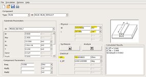
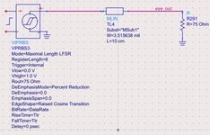
I model it with both TLIN (electrical) and MSUB (physical) model.
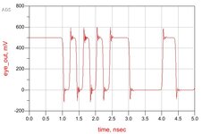
using a 5GHZ data generator to check the signal quality. I found that the result with TLIN model is ok. But the result with MSUB model is bad, still got some ringing.
Both model has Z0=75Ohm and the load is also 75Ohm, also the phase difference is the same, which should be impedance matched.
but why there is the difference? why the MSUB model has ringing even though impedance matched?

lincal.jpg

MSUB.jpg

TLIN2.jpg
MSUB2.jpg
TLIN.jpg
 

Attachments

  • linecal.jpg
    linecal.jpg
    91.8 KB · Views: 139
  • MSUB2.jpg
    MSUB2.jpg
    54.1 KB · Views: 136
  • msub.jpg
    msub.jpg
    44.5 KB · Views: 138
Last edited:

The ringing frequency is in a several 10 GHz range. The microstrip line has other modes than only TEM at this frequency, with different characterisic impedance and propagation delay.

You should excite the line with realistic band limited signal.
 

The ringing frequency is in a several 10 GHz range. The microstrip line has other modes than only TEM at this frequency, with different characterisic impedance and propagation delay.

You should excite the line with realistic band limited signal.
How should I limit other modes and only preserve the TEM mode if this is the way to avoid ringing? using the MSUB model
 

Assuming that your MLIN parameters and MSUB substrate parameters are set properly, the higher order mode effects are real, so it doesn't make much sense to ignore them.

My understanding of FvM's suggestion is to use a low pass filter at the ouput of your signa source, to limit harmonics to realsitiv values. You can find such filters in ADS palette Filters-Lowpass.
 

Status
Not open for further replies.

Part and Inventory Search

Welcome to EDABoard.com

Sponsor

Back
Top