Continue to Site

Welcome to EDAboard.com

Welcome to our site! EDAboard.com is an international Electronics Discussion Forum focused on EDA software, circuits, schematics, books, theory, papers, asic, pld, 8051, DSP, Network, RF, Analog Design, PCB, Service Manuals... and a whole lot more! To participate you need to register. Registration is free. Click here to register now.

Why is LM393 output reduced by half when I connect this?

Status
Not open for further replies.

blapcb

Full Member level 3
Joined
Jan 7, 2007
Messages
188
Helped
2
Reputation
4
Reaction score
0
Trophy points
1,296
Location
Planet earth (most of the time)
Activity points
2,766
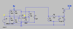
In the attached circuit, I have a comparator (LM393) that takes a sine wave (from pint "A") and produces a 5v square wave (at point "B"). Then it is fed to a limiter circuit to condition it for input to a TTL 3.3v micro.

When only the comparator circuit is present (i.e. other part not connected), I get a nice 5v square wave. But when I connect the second part of the circuit, the amplitude of the square wave at the output of the comparator itself is reduced to about half (and with some distortion).

Why is this happening? I have previously used the same second part of the circuit for conditioning all types of inputs to bring them down to 3.3v and worked fine but not here.

Thanks
 

Attachments

  • Circuit.PNG
    Circuit.PNG
    13.8 KB · Views: 120

The LM393 has an open collector output which you have pulled up with 10k but then you limiter circuit loads that with 10k to ground.

Keith
 

The LM393 has an open collector output which you have pulled up with 10k but then you limiter circuit loads that with 10k to ground.

Keith

I was given to understand this this is required when working with a LM393 (i.e. the pull-up at the output).

The limited circuit is actually part of my device and I can't really change it. It is meant to condition signals (of square wave type) and logical levels from 10v to 40v for use with TTL 3.3v micro.

The comparator circuit, on the other hand, is my attempt to use a sound card as a variable frequency generator for testing (feeding the sine wave in to it and getting a 5v square wave).

So, my "test circuit" is not compatible with my end device? How should I change it so that I can use it in the way I intended? (eliminate the 10K and the output and just connect it directly to the limiter?)

Thanks, appreciate your advice
 

Yes, you need a pull-up. Just make it a lot lower so it isn't influenced by the other circuit as much. Something like 1k or 470 ohms.

Keith
 

Not only R7 loads the output of the LM393 but also the series combination of R8 and C2 (which distorts the signal by delaying it). If decreasing the value of R1 (as posted above) does not solve your problem you can add a voltage follower to the LM393 output. Just take a NPN transistor (eg: BC548/BC547) and connect the collector to +5V, the base to the output of the LM393 and the emitter to the input of the limiter.
Regards
 

Status
Not open for further replies.

Part and Inventory Search

Welcome to EDABoard.com

Sponsor

Back
Top