Continue to Site

Welcome to EDAboard.com

Welcome to our site! EDAboard.com is an international Electronics Discussion Forum focused on EDA software, circuits, schematics, books, theory, papers, asic, pld, 8051, DSP, Network, RF, Analog Design, PCB, Service Manuals... and a whole lot more! To participate you need to register. Registration is free. Click here to register now.

What type of protector to use here?

Status
Not open for further replies.

Zedman

Full Member level 6
Joined
Oct 13, 2003
Messages
331
Helped
9
Reputation
18
Reaction score
6
Trophy points
1,298
Location
Hungary
Activity points
3,511
Hi,

I would like to use this relay: PE014A12 (tyco electronics)

It has only 1 coil and it has to be driven + / - to switch on and - / + to switch off, the question would be how to do it simply and small?

I tought I should use 4 transistors as a H Bridge like thing as used for motors, but use FETs instead?

What type of protector to use here? I used to put in a 1N4001 in parallel with the coil but that won't work here.

I have an MCU output level to control the relay.

thanks,
Zedman
 

how does 1 coil latching relay work

The relay needs a H-Bridge to operate...DOnt waste time on making H bridges urcelf...Check out Full Bridge driver (L298)...Very easy to operate....
 

driving latching relay

I think, the suggestions are a bit oversized. A two-transistor push-pull driver and a series capacitor to achieve the bipolar pulses should be sufficient.
 

latching relay 12v

FvM,

could you please show me some schematics?

thanks,
Zedman

Added after 4 minutes:

It need to fit in a tiny place and will be built with 0603 SMD parts under the relay.
 

12v latching relay

To form the bipolar pulses, you have different options.

My suggestion involves a single push-pull switch (e. g, from two complementary FET), additional level translator transistors would be needed, if the relay supply is different from (above) logic supply. The driver would be controlled by a single static signal and the pulsewidth determined by a coupling capacitor, which needs to have a rather high capacity (e. g. 50 -100 uF).

For a smaller form factor, the said H bridge circuit and pulse shaping at the control side would be required. Driving both bridge halfes speparately from the uC would give minimum part count for this variant. If uP and relay use the same supply, four small FETs make the H-bridge. Or use complementary BJT source followers, with a 3.3V relay and 5V uP supply.
 

1 coil latching relay

What do you think about this solution?

The relay is 12V, the MCU is 3.3V

The only thing missing is where to put the protective diodes?
 

latching relay

The circuit doesn't work for 12 V and would also cause a bridge short during transition. Instead the well-known cross coupled version can be used, Here each high-side driver is controlled through a voltage divider from the opposite bridge output. Of course, it's not allowed to drive both outputs at the same time. This must be considered particularly during uC start-up. Two zener-diodes or four single diodes(respectively two pairs) are needed as protection.
 

1 coil latching

I couldn't see why won't this work with 12V, but i've put it in to a simulator and there's only ~2.5V gets to the motor. I still not see why, but I'll look after it.

Altough I can't see how this could cause short between Vcc+GND, but I assume you were talking about the normal H-Bridge.
 

12v relay driver 3.3v logic

For any driver output between 0.7 and Vcc-0.7, both switches are on. That's what we call a bridge short, usually. Also, for a 12V supply, you would need a 12V driver with this circuit, can't use a HC device.

With the sketched cross-coupled circuit, you can drive the switches from uC directly.
 

h-bridge latching relay

Now u`ll get approx 12v (If Vcc=12) at motor and bridge is no more short....
 

coil latching

No, it surely can't work as drawn in the circuit.

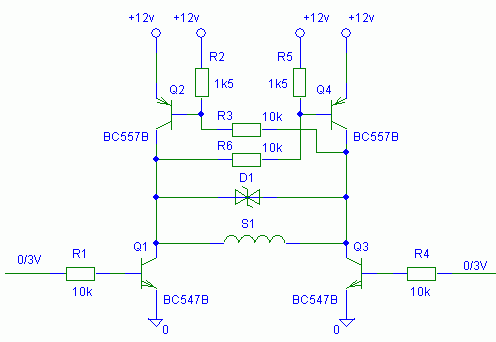
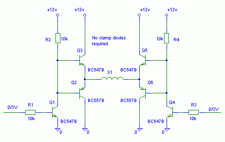
I suggest to check this circuits:
Complementary emitter follower with driver
5_1218209195.gif

Cross-coupled push-pull H-bridge
89_1218209220.gif
 

single coil latching relay driver

Am I missing the point here. If you are using a micro to drive the relay, why don't you use the micro itself to act as a latch to an ordinary relay. The only two reasons that I can think of to do it the way you propose, is to save power, or you do not want the relay to change state if power is removed or applied. Is this the case?
 

2 coil relay

FvM said:
No, it surely can't work as drawn in the circuit.

Pls help me understand why the circuit i drawn above cant work...U need Vbe > 0.7 to saturate the transistor and PNP will saturate at 0V...Why it will not work?
 

full bridge dpdt relay

A supply voltage above 1.4V is unconditionally shorted through the Q1/Q2 base connection.
 

charge capacitor to drive latched relay

Yes it should save power and maintain it's state as it'll run from a .47 uF capacitor psu.

thanks guys I'll build one of FvM's suggestions.
 

Re: coil latching

No, it surely can't work as drawn in the circuit.

I suggest to check this circuits:
Complementary emitter follower with driver
5_1218209195.gif

Cross-coupled push-pull H-bridge
89_1218209220.gif

"four single diodes(respectively two pairs) are needed as protection."
Could you please draw me how to put these single diodes?
 

Re: 1 coil latching relay driving

how to put these single diodes?
From both coil terminals to ground and +12V respectively, as used with most H-bridges.
 
  • Like
Reactions: NickE

    NickE

    Points: 2
    Helpful Answer Positive Rating
Re: 1 coil latching relay driving

thanks a lot
 

Re: 1 coil latching relay driving

will above ckt work for 5v supply..
Not so well, too much voltage drop. Better use a MOSFET H-bridge. There are integrated low voltage H-bridges available.
 

Status
Not open for further replies.

Part and Inventory Search

Welcome to EDABoard.com

Sponsor

Back
Top