Continue to Site

Welcome to EDAboard.com

Welcome to our site! EDAboard.com is an international Electronics Discussion Forum focused on EDA software, circuits, schematics, books, theory, papers, asic, pld, 8051, DSP, Network, RF, Analog Design, PCB, Service Manuals... and a whole lot more! To participate you need to register. Registration is free. Click here to register now.

What is wrong with my opamp gain?

Status
Not open for further replies.

Fred556

Junior Member level 1
Joined
May 23, 2012
Messages
16
Helped
0
Reputation
0
Reaction score
0
Trophy points
1,281
Location
Portugal
Activity points
1,393
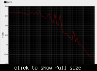
Could someone tell me why my opamp gain is like that?


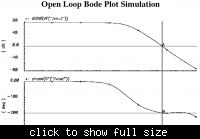
it's suposed to be like this...


thanks in advance, I'm a beginner and I don't know what is the problem...
 

Dear Fred
Hi
I think you forgot to attach your schematic , isn't it ? how i can help you without understanding your problem exactly ?
Best Wishes
Goldsmith
 

Sorry.. I totaly forgot..

schematic opamp:


bench test from book "Baker, 3 editio chapter 24":
 

My line is like in "Zigzag" but I would like only one simple line like the second image in my first post. Do you have any idea why does this "up's and down's"?

I don't know if I explain very well...

thanks for helping me..
 

compensation network? could you give me some examples to search on the internet?

thanks for the help.
 

Google these keywords : frequency compensation , or loop stabilization with compensation network or .....
 
Thanks. I will do it. Thanks again for helping me.
 

My line is like in "Zigzag".......
Do you have any idea why does this "up's and down's"?
A real opamp can not do that. It is impossible.
I think there is a problem with the simulator and how you used it.

I think a proper , compensation network can solve it .
Why do you say that? Did you even look at the circuit? It already has compensation! And he is testing it open-loop, so bad compensation can not cause a problem! In any case, it is impossible for bad compensation to cause a result like that.

compensation network?
The 2.5p capacitor in your circuit is for compensation.
 
Last edited:

Dear godfreyl
Hi
I think that value isn't enough . i told proper value not improper . i know that is compensation network .
Respect
Goldsmith
 

Improper compensation can not cause a zigzag frequency response.
 

Dear godfreyl
Hi
I'm not sure about it . let me ask from my professor about it . i'll find the reason and i'll ask about effect of compensation on zigzag frequency response . Thank you for your remark . because i'm not very expert in compensation effect on problems such as this .
( i'll put here the result )
Best Regards
Goldsmith
 

It will be nice if you can show him the picture so he can better understand the problem.
 

I agree with godfreyl, It should be an issue with simulation setting... may be very few sampled points to plot...whats the number of points per decade (in cadence -> ac sim settings) you are using?
 

I think this kind result is related with simulation precision.
You may increase the cap and res in your test circuit and try again.
 

Status
Not open for further replies.

Part and Inventory Search

Welcome to EDABoard.com

Sponsor

Back
Top