Continue to Site

Welcome to EDAboard.com

Welcome to our site! EDAboard.com is an international Electronics Discussion Forum focused on EDA software, circuits, schematics, books, theory, papers, asic, pld, 8051, DSP, Network, RF, Analog Design, PCB, Service Manuals... and a whole lot more! To participate you need to register. Registration is free. Click here to register now.

What is difference between this two circuit?!

Status
Not open for further replies.

electronicsIUST

Member level 3
Joined
Feb 12, 2017
Messages
67
Helped
0
Reputation
0
Reaction score
0
Trophy points
6
Activity points
575
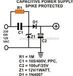
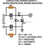
Hi, Can anyone say what is difference between these circuits?! Both of them are capacitor power supply. What is better or there isn't significant difference?!

ace42015c45c9d2940108ff673031659b12a0b1f_small.jpg


1877240dea6bcc501fcf5ebf11406d5d610ba3a7_small.jpg
 

Hi,

First: None of those two supplies is isolated - although they say so.
Touching any pin/signal in this circuit is dangerous!


***
To your question:
The above is connecting GND directely to mains input. While the other is some kind of symmetric regarding input impedance of both wires with respect to system GND.

Especially the voltage rating of the capacitors in the lower circuit is something like "ideal".
It may work in a closed plastic box without any connection (or other conductive piece) to the outside.

None of both has any protectin against mains transiet voltages.
And none has any level of safety.

Klaus
 
If you use the first circuit which has a live/neutral is connected to chassis, I believe there will be a short circuit and fuse will blown up..
 

Hi,

First: None of those two supplies is isolated - although they say so.
Touching any pin/signal in this circuit is dangerous!


***
To your question:
The above is connecting GND directely to mains input. While the other is some kind of symmetric regarding input impedance of both wires with respect to system GND.

Especially the voltage rating of the capacitors in the lower circuit is something like "ideal".
It may work in a closed plastic box without any connection (or other conductive piece) to the outside.

None of both has any protectin against mains transiet voltages.
And none has any level of safety.

Klaus

Thanks, The problem with the second circuit is that it consumes two capacitors, although the voltage ratings of capacitors is halved with respect to that of capacitor in first circuit, but the value of capacitors in lower circuit is doubled. If lower circuit has not significant advantage so I use first.
 

What will happen if in the first circuit phase and null are replaced!?
 

Hi,

functional: nothing
safety: horrible

Klaus
 

Hi,

functional: nothing
safety: horrible

Klaus

What if we put the circuit into cover!?!
Can we avoid this and design a circuit that when phase and null are replaced the circuit dosen't work?
 

Why shouldn't we connect null to our circuit's ground?! the circuit includes a microcontroller.
 

Hi,

There is no general (functional) problem when you connect NULL and circuit_GND.
* But don't call it "isolating" then.
* And you need to take care about safety regulations (of your country)
* you need to consider what happens if somebody mixes up Null and L.
* you are responsible if someone gets hurt or killed.

Klaus
 
The Neutral line is NOT the same as ground.
In a full 3-phase system, the neutral line should carry no net current as that will be balanced by the 3 phase lines.
However, in a single phase situation, the current carried by the phase must also be carried by the neutral line. Also the voltage on the phase line is referenced to the neutral line. They can both float (together) to whatever voltage they like - the circuit will only see the difference between them.
The ground is there for safety purposes only: if there is a connection from either the phase or the neutral line to the chassis then having the chassis grounded means it will take the current and it will not find a path through you when you touch the chassis - the ground connection has a much lower impedance (at least it should) than you do.
Susan
 
It should be clarified that the "ground" symbol designates an internal common node rather than ground. It's a hazardous contact voltage and must be strictly isolated against instrument chassis and any accessible metal part.

Under this prerequisite, both circuits can be used with phase-to-phase supply as well.

Thanks,
But if we had connected the neutral to the ground of our circuit (like first figure) that for example includes a micro controller, it will damage if two phase are connected to the input instead of phase and neutral, is that right?!
 

This is starting to get rather bizarre. Do you really have an idea of what single phase and 3-phase circuits are all about?
In a 3-phase circuit, the three phases carry the voltage at 120 degrees apart - when you add all 3 phases together at any point in time you get zero voltage - which is what the neutral line carries.
In a single phase circuit the voltage occurs between the phase and the neutral lines as a sine wave. In this case there is no other phase to use as a reference for the 'phase' of the sine wave but the voltage will go from the largest positive value, through zero to the largest negative value and back again.
If you look at two phases, they will be 120 degrees apart. That means the voltage between them will be all over the place and will certainly not be sinusoidal. That means there will be all sorts of higher frequencies present and makes for a far more complex rectifier filter circuit. (I know there are 2-phase systems where the voltages are 90 degrees apart but these require different generation techniques and the underlying issue still remains.)
This is one of the reasons why two-phase power systems are very rare with single phase and 3-phase circuits being wide spread.
Also, if you have 3-phase power into your bulding, you will not be making others happy if you produce an unbalanced load on 2 of the phases.
Susan

Thanks for your reply,
Essentially my circuit is designed to produce a fixed voltage from one of phases of a three phase system and neutral to supply a micro controller and some relay. But I should consider what will happen if someone connect two phases to the input by mistake!
 

But I should consider what will happen if someone connect two phases to the input by mistake!
The answer is that you should make no assumptions about power supply earthing and particularly neutral potential in a capacitive power supply. If the ground symbol in your schematic means an external connection (e.g. neutral), you must not use the second circuit and can use the first only under very restricted conditions.

I read the ground symbol as an internal common node, isolated against case and any external circuit. In this case connecting the input phase-phase instead of phase-neutral involve no problems related to power supply earthing, but possibly an unwanted voltage increase.
 
If you look at two phases, they will be 120 degrees apart. That means the voltage between them will be all over the place and will certainly not be sinusoidal. That means there will be all sorts of higher frequencies present and makes for a far more complex rectifier filter circuit.
Susan

I'm sorry but it's a complete nonsense... (except for the first sentence). Do you really mean the rest? Why should be the voltage between two phases (the delta voltage; in a three-phase system) non-sinusoidal and contain "all sorts of higher frequences"? There is no reason for it. If the phase voltage (the voltage between a phase conductor and the neutral conductor) is, say
mimetex.cgi
and sinusoidal, then the delta voltage, say
mimetex.cgi
between two phases will be
mimetex.cgi
and, of course, perfectly sinusoidal...

- - - Updated - - -

... But I should consider what will happen if someone connect two phases to the input by mistake!

The input voltage (i.e. the delta voltage) will be
mimetex.cgi
times higher than in case the right (phase) voltage was used. I comment neither any safety issues nor the circuit components maximum ratings.
 
Last edited:
Why should be the voltage between two phases (the delta voltage; in a three-phase system) non-sinusoidal and contain "all sorts of higher frequences"?
Lets say that one phase is 'sin(x)' and the other is 'sin(x+120)'. Given the difference of 2 sines is 'sin(u)-sin(v)= 2sin((u-v)/2)cos((u+v)/))' then
sin(x)-sin(x+120)=2sin((x-x-120)/2)cos(x+x+120)/2)
= 2sin(-60)cos(x+60)
=-sqrt(3)cos(x+60)
I stand corrected.
And of course I shold have realised that the 3rd phase (which is sinusoidal as well) balances out the other two. Sigh - grey moment!
Susan

Excellent ;-)
 

Status
Not open for further replies.

Similar threads

Part and Inventory Search

Welcome to EDABoard.com

Sponsor

Back
Top