Continue to Site

Welcome to EDAboard.com

Welcome to our site! EDAboard.com is an international Electronics Discussion Forum focused on EDA software, circuits, schematics, books, theory, papers, asic, pld, 8051, DSP, Network, RF, Analog Design, PCB, Service Manuals... and a whole lot more! To participate you need to register. Registration is free. Click here to register now.

Waveform Distortion of 555 timer Pin 6 and Pin 7

Status
Not open for further replies.

sabu31

Advanced Member level 1
Joined
Jan 28, 2011
Messages
446
Helped
12
Reputation
24
Reaction score
13
Trophy points
1,298
Activity points
5,157
Hi all,

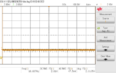
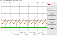
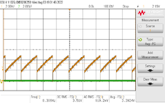
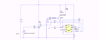
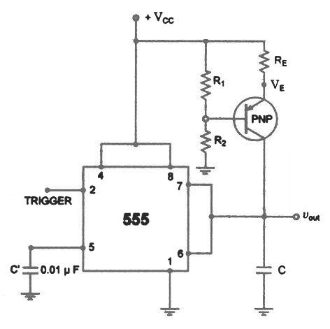
I am facing a peculiar issue with a 555 timer circuit. THe pin 7 and GND has a Saw tooth waveform when measured through a differential probe. This is what is expected. However, I observed that when my fingers are also touching along with signal probes the observed waveform changes to slightly expotential. When I connected both signal probes and differential probes, there is no saw tooth waveforms observed (only a DC signal). What could be the issue for this. I am attaching the three waveforms. The Vcc is 12V.
 

Attachments

  • Both Signal Probe and Differential Probe at the Pin 7 and GND.png
    Both Signal Probe and Differential Probe at the Pin 7 and GND.png
    23.9 KB · Views: 127
  • Pin 7 and  GND with Signal Probe.png
    Pin 7 and GND with Signal Probe.png
    33.5 KB · Views: 137
  • Pin 7 and Gnd with SIgnal Probe and Fingers Touched.png
    Pin 7 and Gnd with SIgnal Probe and Fingers Touched.png
    33.3 KB · Views: 140

Post schematic so we can see values ?

What is model # of probe ?


Regards, Dana.
 

Post schematic so we can see values ?

What is model # of probe ?


Regards, Dana.
I am attaching a LTspice schematic. Are there any simplified method to obtain equivalent function of this circuit
 

Attachments

  • Circuit_EDA.png
    Circuit_EDA.png
    22.5 KB · Views: 154

What are the goals/specs of the circuit, to create fixed freq Sawtooth waves or what ?
Do you care about absolute freq it generates, absolute amplitude it generates....what
is the purpose of the circuit in the grander scheme of things ?.

The PNP looks like a current source to charge the cap, so that produces
a saw, a linear ramp. If you touch that node with a finger you lower the
Z of the current source (read current sources supposed to have infinite
Z, R in this case) and so the current in the cap is no longer just a fixed current,
its in fact a fixed current + a R, the R prodiucing the exponential behaviour you
start to observe.


Regards, Dana.
 

    sabu31

    Points: 2
    Helpful Answer Positive Rating
The ESD "human body model" is 1.5Kohms in series with
100pF. To "somewhere".

While this is a canonical test condition and not a universal
truth, it is indicative of the loading a finger might impose.
 

App,lying the human body model to the basic circuit one can see as its swept from
0 pF to 100 pF what the ramp does.

1659569716442.png


Regards, Dana.
 

    sabu31

    Points: 2
    Helpful Answer Positive Rating
What are the goals/specs of the circuit, to create fixed freq Sawtooth waves or what ?
Do you care about absolute freq it generates, absolute amplitude it generates....what
is the purpose of the circuit in the grander scheme of things ?.

The PNP looks like a current source to charge the cap, so that produces
a saw, a linear ramp. If you touch that node with a finger you lower the
Z of the current source (read current sources supposed to have infinite
Z, R in this case) and so the current in the cap is no longer just a fixed current,
its in fact a fixed current + a R, the R prodiucing the exponential behaviour you
start to observe.


Regards, Dana.
The objective is to adjust the frequency of saw tooth signal based on the input current.

The pnp acts like a current source. However whats the function of NPN. I tried to replace NPN with pulse generator in simulation however the system does not work.

Why is the differential voltage probe not working with this system in actual circuit .The differential probe should have isolation right so its should be affect the waveform?

Are there any references for a better method of current controlled 555 timer frequency circuit.
 

NPN looks like a sharp reset of sawtooth.....? Not sure myself because its 10n
caps look too small to me to completely reset the falling edge of saw.

1) What freq range do you want ?
2) What is current range for that freq range ?
3) What is linearity goal ?
4) What is model number of your diff probe ?
5) Do you want fixed amplitude over the freq range of the sawtooth ? if
so what is amplitude goal in volts ?
6) Does saw wave want to be ground referenced or start at some other + or - voltage ?
7) Can you comment on what actual use of circuit is for, what the waveform is used for ?
8) What power supply voltages do you have to run circuit ?

This is overkill but a quick way of getting what you want -

1659610347479.png


Regards,. Dana.
 
Last edited:

NPN looks like a sharp reset of sawtooth.....? Not sure myself because its 10n
caps look too small to me to completely reset the falling edge of saw.

1) What freq range do you want ?
2) What is current range for that freq range ?
3) What is linearity goal ?
4) What is model number of your diff probe ?
5) Do you want fixed amplitude over the freq range of the sawtooth ? if
so what is amplitude goal in volts ?
6) Does saw wave want to be ground referenced or start at some other + or - voltage ?
7) Can you comment on what actual use of circuit is for, what the waveform is used for ?
8) What power supply voltages do you have to run circuit ?

This is overkill but a quick way of getting what you want -

View attachment 177826


Regards,. Dana.
Thanks Dana for the reply,

I am attaching the datasheet of the differential probe. Is there any reference circuits for such type of requirement
 

Attachments

  • CT4196_datasheet-1588501.pdf
    604.9 KB · Views: 147

Thanks Dana for the reply,

I am attaching the datasheet of the differential probe. Is there any reference circuits for such type of requirement
You have to answer the questions on design requirements in post #8.....?

The diff probe is not real hi Z, its 500K to ground, so that would load the
cap being charged by current source and cause the exponential rather than
pure ramp behaviour of waveform. As I showed in post #6.

1659615027484.png


Regards, Dana.
 
Last edited:

    sabu31

    Points: 2
    Helpful Answer Positive Rating
You have to answer the questions on design requirements in post #8.....?

The diff probe is not real hi Z, its 500K to ground, so that would load the
cap being charged by current source and cause the exponential rather than
pure ramp behaviour of waveform. As I showed in post #6.

Regards, Dana.
Thanks Dana for the reply.
When I am putting 500k resistance across the pin 6, it shows same effect. How do we then measure differential voltages in this circuit.

Regarding the circuit requirements, unfortunately, I don't have all the details. Its used for timing which will drive another circuit.

When I am checking for saw tooth waveform generators, all circuits show similar circuit as shown

However, in this the output pin 3 is also tied to Control Voltage (5). What is the function of pin 5 and 3 in this circuit? In pin5 a sharp dip is observed in the voltage , is this trigger to reset the saw tooth.
 

I am afraid w/o design goals I cannot be of much further help.

Regards, Dana.
 

Hi,

That's a complicated circuit to analyse... Why not have a normal 555 astable pin 3 output drive a current source of your choice and also drive an NPN inverter, which in turn controls an NPN that drains the capacitor when the timer output is low? The current source is really tricky due to Iout vs dTemp, a dedicated, quality current source (e.g. not LM334) should be easier (and maybe cheaper) to buy than try to make with discrete parts...

555: check if SA, LMC, etc. also meet your temperature and/or Vsupply drift error budget.

Buffer probes with op amps: Zin = infinite... or at least more than 500k, maybe 10M or even 10G.
 
An instrumentation amplifier with decent front end
and slew / BW attributes would do the job, and may
be a "bench doo-dad" worth keeping around if you
go to the trouble of wiring it up.

When I want a triangle wave that's current controlled,
I will use a 1X source, switched 2X sink current mirror
pair, a pair of comparators and a SRFF. Tougher to
get a real sawtooth that acts real linear (f vs I) due to
the finite, fixed-ish discharge stroke interval, but the
same scheme.

Now UCxxxx PWM parts have a more saw-tooth-y
oscillator and you could substitute perhaps a current
port, for the timing resistor and see a waveform more
like you'd prefer on the timing capacitor. This might
want buffering before you send it off into the woods,
it's not meant for drive.
 
Hi all,
Just as a continuation with this post, I want to know whats the modeling for a passive probe with 10x attenuation. I am able to get desired waveform when I connect passive probe with 10x setting at the pin 7 of the 555 timer. I am trying to recreate this with 10pf capacitance in LTSPICE but not showing much effect
 

I want to know whats the modeling for a passive probe with 10x attenuation. I am able to get desired waveform when I connect passive probe with 10x setting at the pin 7 of the 555 timer. I am trying to recreate this with 10pf capacitance in LTSPICE but not showing much effect
A 10X oscilloscope probe has a 10 megaohm resistance with somewhere in the neighborhood of 10pF capacitance to ground.

10pF is a small capacitance compared to the charging capacitor, so why would you expect a noticeable effect?
 

    sabu31

    Points: 2
    Helpful Answer Positive Rating
However, in this the output pin 3 is also tied to Control Voltage (5). What is the function of pin 5 and 3 in this circuit? In pin5 a sharp dip is observed in the voltage , is this trigger to reset the saw tooth.

Pin 5 is designed to vary duty cycle. In doing so it also changes frequency.

Apply low voltage for low duty, high voltage for high duty. It's hard to predict the effect when you connect it to Pin 3 output.

From what I can tell current generally flows out of pin 5. Resistance must not be too great. Which is to say you must try your own experiments.
 

It has been explained why a low-impedance probe or a finger affects circuit operation. IMHO it's unrealistic to model the finger by HBM model with series capacitor in this context, for the low frequency range you should rather consider a higher kOhm load.

I want to supplement that the usage of CV pin 5 as trigger input is unusual, I haven't yet seen a manufacturer application circuit using it in this way. It's described in datasheet only as optional modulation input. In so far the datasheet is no specific help when you analyse circuit operation. Nevertheless should a simulation with transistor level model show the correct behaviour. LTspice uses an ideal NE555 models which has minor differences to real device, e.g. not exposing substrate diodes for all pins. Respectively you get an undershoot at pin 5 that is cut to -0.6 V by the real device.
 

Forest Mims used it in his lab notes book, see attached. Of course with no specs
on that pin one is designing with one eye closed.

Looks like simple input to comparator biased with internal string :

1662725256301.png


1662725482418.png

Regards, Dana.
.
 

Attachments

  • Forrest Mims - Optoelectronics Circuits.pdf
    4.1 MB · Views: 132
Last edited:

" The objective is to adjust the frequency of saw tooth signal based on the input current. "

there are better circuits to achieve this - one has been described above - the classic VCO

for a CMOS 555 ( better than the BJT ones ) the timing cap goes between 1/3 to 2/3 Vcc ( for pin 5 left alone ) - if this if OK, then a current source to the cap, with pin 7 discharging rapidly ( say 47 ohm ) will give the linear rise and sharp fall you are possibly seeking.

Now you need only design the current source - remember low current = low freq and vice versa

It would pay to look up current mirrors and current sources so you can ground reference the control and possibly have 1 - 5V input = freq range of VCO.
 

Status
Not open for further replies.

Similar threads

Part and Inventory Search

Welcome to EDABoard.com

Sponsor

Back
Top