Continue to Site

Welcome to EDAboard.com

Welcome to our site! EDAboard.com is an international Electronics Discussion Forum focused on EDA software, circuits, schematics, books, theory, papers, asic, pld, 8051, DSP, Network, RF, Analog Design, PCB, Service Manuals... and a whole lot more! To participate you need to register. Registration is free. Click here to register now.

[SOLVED] Voltage To Current Converter Suitable Topology

Status
Not open for further replies.

mamech

Full Member level 3
Joined
Nov 9, 2010
Messages
176
Helped
0
Reputation
0
Reaction score
0
Trophy points
1,296
Activity points
3,135
Hello all

I want to convert a voltage signal to a current signal. when I searched I found this is the most simple topology that achieves this objective:
https://sub.allaboutcircuits.com/images/03039.png

it works very well with me, with only one draw back : the current signal is not referenced to the ground
and in my application I need the output current to be referenced to the same ground of opamp supply.

so I searched again, and I found this topology:
**broken link removed**

it works, but it is not accurate like the first method. for example, I used all resistors to be 255 ohms (including load resistor), and when I gave it 4.9 volts input, I got drop on load resistor around 4.56 volts.

Is not there a simple topology that is accurate like the first method, and referenced to ground like second method?
 
Last edited:
Re: Voltage to Current Converter Suitable Topology

Hi,

your headline says "Current to voltage", but your post says "voltage to current". Please clarify.

***
There are a lot of informations missing:
* What is your supply voltage?
* What OPAMP do you use?
* What is your signal input voltage range?
* what is your output current range?
* or: what is your desired I/U ratio?

Please show only circuits/schematics/pictures that show exactely YOUR test circuit.
Please show schematics with all informations at once: Power supplies, part values, part names...

Klaus

Sorry I wrote it wrong when I put the title. I think that it is not editable

* What is your supply voltage?
unregulated adaptor around 14 volts vcc output.
* What OPAMP do you use?
Lm358
* What is your signal input voltage range?
0 to 5 (arduino pwm output)
* what is your output current range?
0-20 mA (as I am using 255 ohms instead of 250 ohms resistors, it will give an output a little lower than 20mA, it would be about 19.6 m A , and it is acceptable to me)
* or: what is your desired I/U ratio?
0-5 => 0-20 mA (the first schematic shows the input varies from 1 to 5 volts, but this is not a problem because I control the output range from arduino)

the schematics shown are exactly what I applied.

thanks
 
Last edited by a moderator:

What are all the resistor values?
Those aren't shown on the schematic.

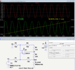
Below is an LTspice simulation of a slightly modified circuit with an added 255 ohm resistor to allow equal value bridge resistors.
It shows a peak output current of 20mA for a 5V peak input as the output load varies from 0 to over 400 ohms.

Capture.PNG
 
Last edited:
  • Like
Reactions: mamech

    mamech

    Points: 2
    Helpful Answer Positive Rating
it works, but it is not accurate like the first method. for example, I used all resistors to be 255 ohms (including load resistor), and when I gave it 4.9 volts input, I got drop on load resistor around 4.56 volts.

Thinking might help. Requiring 20 mA output into RL for an all 250 ohms dimensioning requires LM358 to source 40 mA, far beyond guaranteed 20 mA output current.
There are other possible variants of the Howland current source that with less internal power dissipation, e.g. the circuit suggested by crutschow. A principle disadvantage is the output impedance degradation caused by resistor mismatch. But it's surely better than your results suggest.
 
  • Like
Reactions: mamech

    mamech

    Points: 2
    Helpful Answer Positive Rating
What are all the resistor values?
Those aren't shown on the schematic.

Below is an LTspice simulation of a slightly modified circuit with an added 255 ohm resistor to allow equal value bridge resistors.
It shows a peak output current of 20mA for a 5V peak input as the output load varies from 0 to over 400 ohms.

View attachment 138605

worked fine! then the reason was that the op am could not deliver all this current. many thanks for help!
 

Status
Not open for further replies.

Part and Inventory Search

Welcome to EDABoard.com

Sponsor

Back
Top