Continue to Site

Welcome to EDAboard.com

Welcome to our site! EDAboard.com is an international Electronics Discussion Forum focused on EDA software, circuits, schematics, books, theory, papers, asic, pld, 8051, DSP, Network, RF, Analog Design, PCB, Service Manuals... and a whole lot more! To participate you need to register. Registration is free. Click here to register now.

Voltage stabilization in the car

grabber

Newbie
Joined
Jul 14, 2023
Messages
4
Helped
0
Reputation
0
Reaction score
0
Trophy points
1
Activity points
43
I have a car with canbus. When the engine is off, the voltage graph is constant. When the motor is on, the voltage is alternating (peaks). I have a led light controller that works fine when the engine is not running. When I turn on the car, the controller stops working properly. How to make a filter (stabilizer, capacitors) to keep the voltage waveform without drops all the time?
 
Hi,

I recommend to analyze the voltage first:
* with scope pictures
* with frequency analyzer

Also wrong wiring could cause this problem.

Klaus
 
OK, I will try to expalne better:

I have DC current, pulsating from 0 to 12v (square wave). I need to stabilize this current to get DC current without pulsating (12+ still, high). I wanted to use the LM7812 type stabilizer with the appropriate capacitors. Question: what and where to use capacitors? I know the LM7812 gives a voltage drop, but it doesn't need the full 12v, it just needs to get a stable voltage without pulsing.

I using led strip controler, which works badly when the current becomes unstable (work from a car alternator). When the voltage is directly from the battery it works fine. I need to make a filter to get constant voltage. The load is about 400 mA.
 
If you put a diode in series with input, and a significant Cap at input
to ground, then the Cap can function as a supply to the 7812. Use
Q = C x V, or I = C dV / dT. Solve for C, plugging in the drop in V
max before 7812 drops out of regulation, and use dT to make C large
enough to span the input drop. And of course you have I.

The diode of course keeps the source from robbing the 7812 input
supply when it is much lower.

Something like this :

1689390198654.png


Note the ripple rejetion of the 7812 much better than what sim shows, I think the
spice model I am using may not be accurate. The input cap size you can play with,
just use computation done earlier. Also I did not put an output cap, that will help
with ripple as well.


Regards, Dana.
 
Last edited:
OK, I will play with it... I don't have a workshop power supply to test it so I hope it will work without fire ;)

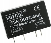
In fact, I have one more idea to separate it directly from the canbus powered line via a relay. I have a semiconductor relay DD2203HK in stock. I was thinking of using it similarly with a 1uF 16v capacitor. Will a diode be needed? In this case I will take 12v by load pins directly from battery... What do you think?
 

Attachments

  • Screenshot_20230715-081717_Allegro.jpg
    Screenshot_20230715-081717_Allegro.jpg
    180 KB · Views: 54
Last edited:
I'm not sure why a relay is needed at all and in any case an SSR only works on AC.

We have no idea how your device reacts when the supply varies but looking at it simplistically, what you are trying to do is make a stable 12V supply out of an unstable one. I would suggest trying this first:

1. Get yourself a Low Drop Out (LDO) voltage regulator rated at 12V and 1A or more,
2. Get yourself a Schottky diode rated at 1A or more.
3. Get yourself an electrolytic capacitor rated at 35V with a value at least 2,200uF, more is better.
4. Get yourself an electrolytic capacitor rated at 16V with a value of 2.2uF.
5. Take your existing positive supply wire, connect it to the anode of the diode, connect its cathode to the input of the regulator,
6. connect the big capacitor (step 3) positive end to the junction of the diode and regulator input and its negative end to ground.
7. connect the small capacitor (step 4) positive end to the output pin of the regulator and its negative end to ground.
8. connect the ground pin of the regulator to ground. Ground in this case would be the negative side of the supply.

Now if you take the 12V to your LED strip controller it will draw current through the diode and regulator using the big capacitor as a local power reservoir. The diode will prevent the reservoir flowing back to source if the incoming voltage drops below 12V so it should stay 'topped up', at least for as long as needed while the power dip passes.

Brian.
 
Note the ripple rejetion of the 7812 much better than what sim shows, I think the
spice model I am using may not be accurate
It's not the model problem. What you see is rather realistic.
The problem here is that the regulator can't regulate, because it is in (min.) dropout mode.

Again: Analyzing the proplem is the first step to go.

I have DC current, pulsating from 0 to 12v (square wave)
This is rather confusing.
Current can not be measured in Volts.
Also, when a battery is involved - and it usually is involved when the engine runs - then you will never see 0V/12V square wave.
I even doubt that the current from an alternator is square wave shape.

--> Show wiring and the according scope pictures.

Klaus

Using D + C:
* with a noisy supply you catch the peaks. And when the peaks are of high energy it may result in rather high capacitor voltage.
* with a quiet supply it drops the voltage ....
So in one case the voltage may become too high, and in the other case too low. None of both may be a satisfying result.

May, maybe, guessing... --> leads to: trial and error, unreliable results, killed devices... loss of time and money
--- Updated ---

in any case an SSR only works on AC.
There are SSRs for AC load, for DC and for both.
The shown one is for DC load.
The pure AC ones work with triacs, the others usually work with MOSFETs.

Klaus
 
Last edited:
Note the ripple rejetion of the 7812 much better than what sim shows, I think the
spice model I am using may not be accurate
It's not the model problem. What you see is rather realistic.
The problem here is that the regulator can't regulate, because it is in (min.) dropout mode.

Thanks Klaus for picking this up. As I was doing the sim I was thinking this is a crappy regulator
with high dropout, my age is showing.

Also, when a battery is involved - and it usually is involved when the engine runs - then you will never see 0V/12V square wave.

I did that because it is extreme case, no other particular reason.

Here is a little better look, excluding load dump issues.

1689418766341.png


Of course we have failed to discuss load dump and general vehicle transient protection for design.

1689418813291.png


https://www.ti.com/lit/an/snva681a/snva681a.pdf?ts=1683122330275&ref_url=https%3A%2F%2Fwww.google.com%2F

https://m.littelfuse.com/~/media/el...e_load_dump_standard_application_note.pdf.pdf

https://www.st.com/resource/en/appl...nd-component-selection-stmicroelectronics.pdf

https://eds.st.com/tvs/#/ Design tool


Regards, Dana.
--- Updated ---

Obviously a LDO overall a better choice because the vehicle probably
not generate the 14V+ to consistently keep the reg in its linear region.


Regards, Dana.
--- Updated ---

Of course one can always use a L :

1689421649666.png


Regards, Dana.
 
Last edited:
You just want 12V and 400mA, and youR vin is varying.?
From what voltage to what voltage is it varying? (the input)

...Then just buy two SMPS regulators.......put them in cascade.....one to boost up to some intermediary voltage, then one to buck down to your 12v 400mA.
 
OK, one of movie below is when engine is off, second one is when engine is on. Led strip is connected to battery negative and to +12v in turn light. Lights in car are controled by module, without relay. When I connect positive wire directly to battery positive pin, it is working fine. Problem is when is connected with wire in lamp. Even if plug is connected or disconected with lamp. So problem is with +12v taked from lamp. Inside lamp there is normal light bulb. When I connect normal relay to lamp it working fine... So easy way is taking 12v from battery and control it by relay by headlight but... I hate this tick tick tick tick tick... sound from normal relay. I tried LM7812 with 2 caps - 1uF 60v on input and output but it not helped. Maybe I shoud use bigger one??


Attachments

  • 20230704_183611.mp4
    12.4 MB
Last edited:
Hi,

I guess it would annoy you if I ask again for the same information...
So I´ll better leave.
Good luck.

Klaus
 
OK, so you have a car with "normal" indicators.....but now you have fitted led strip indicators also....and you want these to light up aswell, when your "normal" indicator flashes.?

...So why did you not just connect them in parallel with the "normal" indicators?...presumbaly because they dont take the same voltage as needed by your led strips?.........sorry, but i am not a "car" person, and i dont know car electrics...but if you give a schem...
 
Lately I have my bargraph voltmeter telling my car's voltage. LED's light immediately in response to voltage.

Usually it lights only 1 led (14 or 15 V) indicating stable DC. With engine off it's the 12 or 13V led.

Then at times I too see it changing rapidly over a few volts range. So rapidly that led's 12-15 V appear to be on simultaneously. I suppose these waveforms come from the alternator. None of the car's appliances give a hint that the system voltage has an AC component.

I have not figured out what makes the difference, whether it's:

* A/C operating full, or

* compressor off while A/C operates partially, or

* quirky battery terminals, etc.

My voltmeter uses a 3914 IC and 10 led's. It plugs into the 12V socket.

----------------------------------------------------------------

Below is a method to filter noisy DC supply and improve stability to sensitive devices.

I run it in Falstad's animated interactive simulator. Free to download and use at:

falstad.com/circuit


Clicking the link above:

1) Navigates to website falstad.com/circuit.

2) Loads my schematic into the simulator.

3) Runs it on your computer.

Select Toggle full screen in the File menu.

Right-click on a component to change parameters.

The scope trace has two volt readings superimposed:
* power supply with triangle wave riding @ 20 Hz.
* filtered DC 12V within 0.3 V).

30,000 uF capacitor looks okay in theory although you can try different values.
The 2 ohm resistor has an isolating effect, enhancing smoothing action.

filter noisy supply via resis-and-cap to sensistive device.png
 
Last edited:

LaTeX Commands Quick-Menu:

Similar threads

Part and Inventory Search

Welcome to EDABoard.com

Sponsor

Back
Top