Continue to Site

Welcome to EDAboard.com

Welcome to our site! EDAboard.com is an international Electronics Discussion Forum focused on EDA software, circuits, schematics, books, theory, papers, asic, pld, 8051, DSP, Network, RF, Analog Design, PCB, Service Manuals... and a whole lot more! To participate you need to register. Registration is free. Click here to register now.

voltage regulator switching frequency logic

yefj

Advanced Member level 4
Joined
Sep 12, 2019
Messages
1,195
Helped
1
Reputation
2
Reaction score
3
Trophy points
38
Activity points
7,217
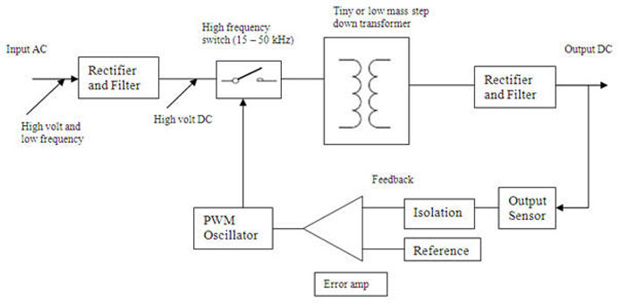
Hello , in the video bellow at 11 minute they say that higher switching frequency the smaller components we can use.
What is the logic that i could understamd why higher switchng frequency allows smaller components?
How can i link the switching frequency to the component size i could use?
Thanks.


The higher the switching frequency, the smaller the inductors and capacitors can be.

Of course, you could have found this out yourself by searching "switching frequency vs. component size".
 
Hello Barry ,I have found the manual shown below . But I can’t see the physical logic between the two.
 
Hello Barry, the switching causes the capacitors and inductors to charge and discharge.
by the formula below if our Fsw is larger then our ripple voltage is hight then our capacitor could burn
smaller capacitor mens smoller voltage rating.
So why higher switching is anaibling the use of smaller capacitor /inductors?
Thanks.
1710521091668.png
 
Smaller values, not smaller power ratings!

However, consider the size/weight of a low frequency iron cored transformer to a small lightweight Ferrite one and the size/weight of large electrolytics compared to ceramic capacitors.

Brian.
 
Hi,

if I wanted to fill a bathtub of water within one hour .....
* I could use a big bucket
* or I could use a cup .. but needs more/faster movements (higher frequency)
* or I coud use a spoon and need to be even faster (even higher frequency)

Klaus
 
Hello, from the ripple formula I see that when Fsw is increase then C will be decreased to keep the same value of ripple .

But ripple in the DC supply is a bad thing we are looking on the avarage value of the DC .
So why are we looking at the ripple peak and not the avarage whole signal ?
Thanks .
 
Both L and C are per unit length parameters in MLCC with many multiple layers required for large values. Depending on the geometry of the MLCC internal design, the ESL and C(parasitic) and assumptions of measurements with pad designs are not always predictable or linear. Datasheets need to be verified, in case something is overlooked , like conductor surface roughness on u-wave path length and ground proximity effects or Er effects inside a shielded enclosure for u-strip, when transition rates are >> 1GHz.

Some dominant time domain relationships are;
τo=√(LC)=1/ωo, τ =L/DCR, Zo=√(L/C)
Thus small LC values are needed to reduce time delay.


Does it make more sense now to shrink component length with values for shrinking values for time delay,τo, while maintaining damping factor?

When precision is needed for high Q reactive components, low Er (NP0/C0G)) and air coils are used inside shielded boundaries with minimal pF.
The ratio of stored/load energy in closed loops is an important metric as the BW is a function of high Q resonance and phase abruptly shifts at centre.

Ripple is essential for feedback in order to sense and regulate output. It can never be eliminated.
The gain and ratio of impedances of load to source for all RLC parameters determines the attenuation of ripple and also cause of overshoot results.
Phase lead (type III) compensation is used to improve phase margin as well as ZVS , current feedback and other mechanisms.

Since power ratings also reduce with losses in smaller case sizes, and dissipation factors may be constant, multiple parallel C+ESR are benefitial to reducing ripple.

But don't get tied up in knots over it.
 
Last edited:

LaTeX Commands Quick-Menu:

Part and Inventory Search

Welcome to EDABoard.com

Sponsor

Back
Top