Continue to Site

Welcome to EDAboard.com

Welcome to our site! EDAboard.com is an international Electronics Discussion Forum focused on EDA software, circuits, schematics, books, theory, papers, asic, pld, 8051, DSP, Network, RF, Analog Design, PCB, Service Manuals... and a whole lot more! To participate you need to register. Registration is free. Click here to register now.

Voltage Loss in Integrator

Status
Not open for further replies.

OsmanH

Newbie level 6
Joined
Aug 11, 2011
Messages
14
Helped
0
Reputation
0
Reaction score
0
Trophy points
1,281
Activity points
1,377
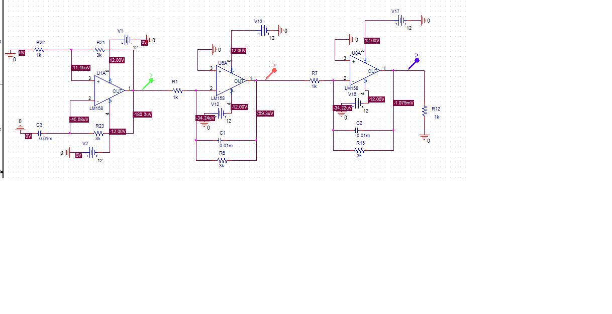
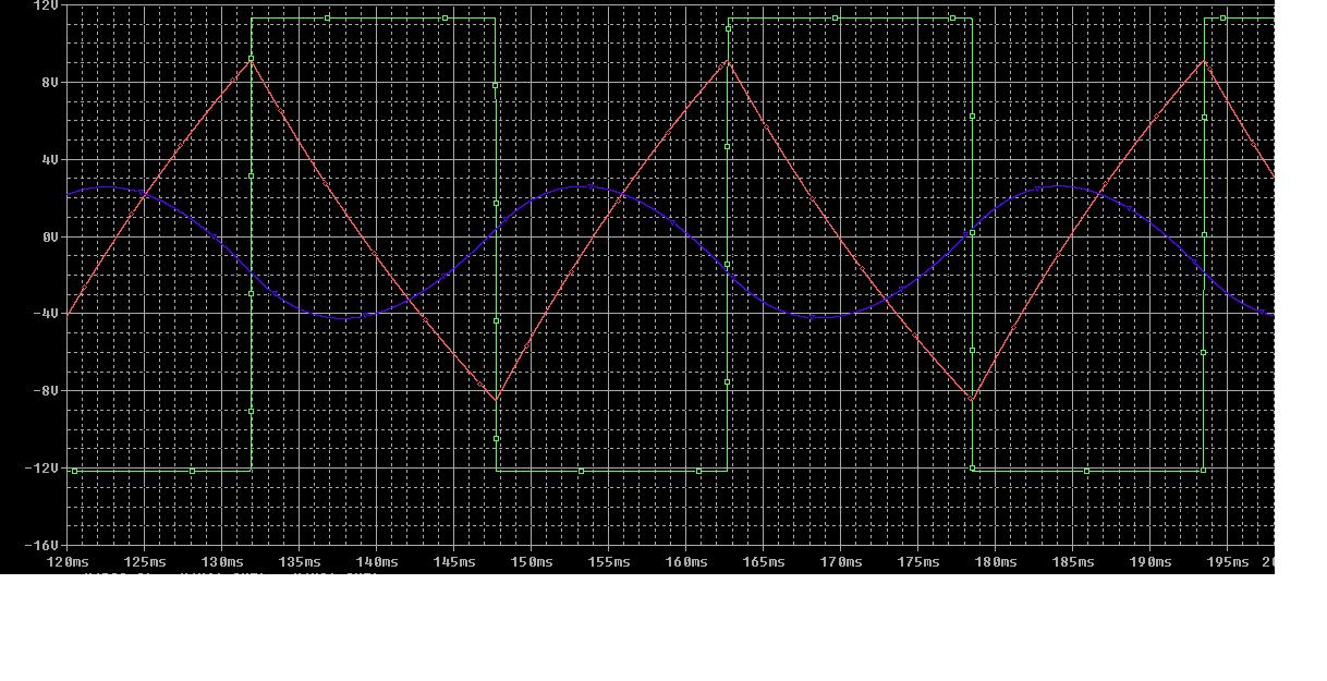
Hi, I designed a function generator that converts square wave to sine wave but i had a voltage loss in output signal. How can I boost the voltage of output signal. I changed values of components of integrators but cant find it. Anyone can say me what should i do? Here is the schematic and simulation graphic.


Thank you for helping
 

Hey buddy!
How you design this circuit? my mean is this values are unusual!
the slew rate of your op amps should increase. i think your problems are :
SR percent(you should change your op amps .)
and you should correct the value of your elements.
with which formula you obtained these values??????!!!!!!!!
Best regards
Goldsmith
 

the slew rate of your op amps should increase. i think your problems are :
SR percent(you should change your op amps .)
and you should correct the value of your elements.
Completely wrong, except for the last words.

Simply increase the gain of the integrators respectively. Because the 1k resistor is already rather low, you can reduce the capacitor value (and most likely increase the lossy parallel R respectively). Just play around with the values a little bit.

By the way, the "sine" waveform looks better, than I expected in a previous post. I think, you're almost done.
 
  • Like
Reactions: OsmanH and LvW

    LvW

    Points: 2
    Helpful Answer Positive Rating

    OsmanH

    Points: 2
    Helpful Answer Positive Rating
Why 3k resistors in parallel to the feedback C ? I propose a much larger value.
What is the repetition frequency of the squarewave? The corner frequency of the "integrators" (in fact: lowpass of 1st order) should be smaller at least by a factor of 10.
 
  • Like
Reactions: FvM

    FvM

    Points: 2
    Helpful Answer Positive Rating
Dear friends
Hi
thank you for your attention.
if you consider it: with an opamp with low slew rate we can to obtain a good integrator!!!!! it is fulse. one of bets of design is have an op amp with high slew rate . and for next step : in integrators , value of capacitors are important.
and input resistor is as current source selector. so thus its value is most important.
for next step for integrator design , we have some formula. so designing is very simple. so if you thake integral from square wave you will have triangular wave and if you take integral from triangular wave you will have a sine wave with 1/2 of amplitude of triangular wave. you can amplify your out put amplitude.
Sincerely
Goldsmith
 

......
with an opamp with low slew rate we can to obtain a good integrator!!!!! it is fulse. one of bets of design is have an op amp with high slew rate
...........
and input resistor is as current source selector. so thus its value is most important.
..............
if you take integral from triangular wave you will have a sine wave

Hi goldsmith,

I think some comments/corrections are in order.
At first, the slew rate has - in principle - nothing to do with a "good" integration process. The slew rate has the same influence on the operating range as is the case for each opamp amplifier. Much more important is the input offset voltage, since this parameter disturbs the integrating properties of the circuit (it makes a feedback resistor necessary).
The input resistor - as one of two passive components - is not "most important" - it is as important as each part in an analog circuit.
More attention should be paid to the selection of the resistor Rp in parallel to the integrating capacitor.
Rp changes the integrator to a 1st order lowpass and determines the cut-off frequency - and that's the reason I have asked OsmanH for the operating frequency (repetition rate).
At last, taking the integral from a triangular wave cannot result in a sinusoidal wave. Instead, it is a first-order filtered version of the triangle that may look similar to a sinusoidal signal. A second-order lowpass would do a much better job.
 
  • Like
Reactions: FvM

    FvM

    Points: 2
    Helpful Answer Positive Rating
Dear LvW
For example time of rising in triangle is 2ms and its max voltage is 5 volts i think we need an op amp with slew rate:sr=dvo/dt= 2500. is it correct?
Thank you for your attention
 

Slew-rate limitations have to be considered for any OP circuit involving AC signals. But although LM358 is a slow OP, it's available slew rate (about 0.7V/µs) is several orders of magnitude above the signal slew rates present in the circuit (≈ V/ms). That's why your considerations are hard to understand and effectively unrelated to the problem raised by the original poster.
 
  • Like
Reactions: LvW

    LvW

    Points: 2
    Helpful Answer Positive Rating
Dear LvW
For example time of rising in triangle is 2ms and its max voltage is 5 volts i think we need an op amp with slew rate:sr=dvo/dt= 2500. is it correct?
Thank you for your attention

Goldsmith, in addition to FvM's answer - I agree by 100% - I like to remind you that the slew rate has to be given in voltage/time (in most cases: volts/µsec). A simple number as mentioned by you says nothing.
 
  • Like
Reactions: FvM

    FvM

    Points: 2
    Helpful Answer Positive Rating
2500 means apparently 2500 V/s (respectively 0.0025 V/µs). Similar slew rate numbers can be expected for battery operated micropower OPs, but not for a general purpose OP, even a slow one.
 

2500 means apparently 2500 V/s (respectively 0.0025 V/µs).

Yes, I could imagine. Nevertheless, I prefer technical information that do not require some sort of speculation.
 

I have a another problem about frequency. I want to increase the frequency about 10Mhz. I changed value of capacitors but I cannot reach 10Mhz. What should I dofor it? Anyone can give me an idea?
 

10 MHz "sine" frequency? You'll need fast OPs from the 100 MHz GBW class. Do you have any of these available?
 

Actually I want 10MHz square wave in relaxation oscillator
 

Can someone help me about frequency?

Thank You
 

Can someone help me about frequency?
Thank You

OsmanH, why don't you try to express yourself more clear?
What means "about frequency"?
Do you want to integrate a squarewave with a repetition rate of 10 MHz (Because, up to now we spoke about integration only)?
Or do you want to generate such a signal?
 

Yes I want to integrate a squarewave with a repetition rate of 10 MHz
 

Status
Not open for further replies.

Similar threads

Part and Inventory Search

Welcome to EDABoard.com

Sponsor

Back
Top