Vermes
Advanced Member level 4

It is a circuit with energo-electronical converter DC/AC. It was built to control a three-phase induction engine through the inverter. Two vector methods of control, the so-called DTC were implemented for this construction. The circuit is not limited to one method and if you want, you can use other vector methods.
The picture below shows the structure of control of the circuit with microcontroller STM32F407VGT6.

The control circuit is based on signal microcontroller (DSC) STM32F407VGT6. The controlling part showed in the picture above consists of the following blocks:
- power supply 5V and 3,3V, analog 5V and 3,3V and separated voltage 5V
- adapter, the PCB with microcontroller STM32F407VGT6 and the necessary components (capacitors, resistors, quartz oscillator) and derived all the pins in raster 2,45mm
- SWJ-DP connectors for programming and debugging the microcontroller from the PC
- analog part with the connector for analog signal transmission from the measure part and two potentiometers
- three control buttons and connector for connecting the alphanumerical LCD display
- connector for communication through SPI with bipolar 12-bit converter AD5724 from Analog Devices
- two derivations of signals with DAC converters built in the microcontroller
- galvanically isolated encoder interface
- interface generating signals that control the converter keys with the watchdog-timer and the buffer cooperating with it
- interface RS232 for communication with the PC
- eight-diode LED bar
Galvanically isolated measure part was built of:
- three current sensors ACS712
- voltage measure circuit with HCPL7800 with operational amplifier adjusting voltage to STM converter
When you want to use the processor on amateur boards, it is recommended to design an adapter. It is a form of adapter from SMD to HEADERS, on which there is a crystal quartz and passive components necessary for operation. The below picture shows the adapter:
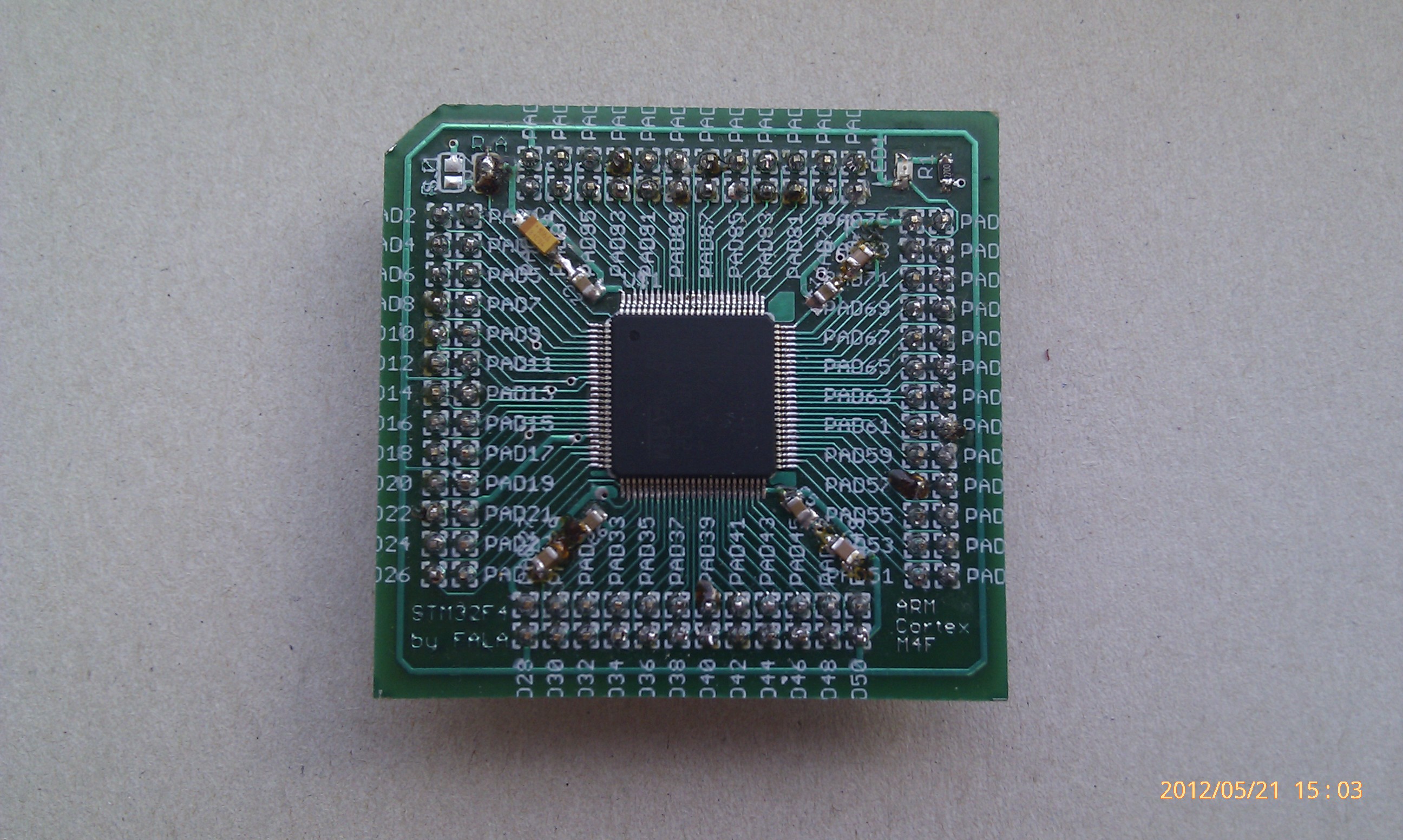
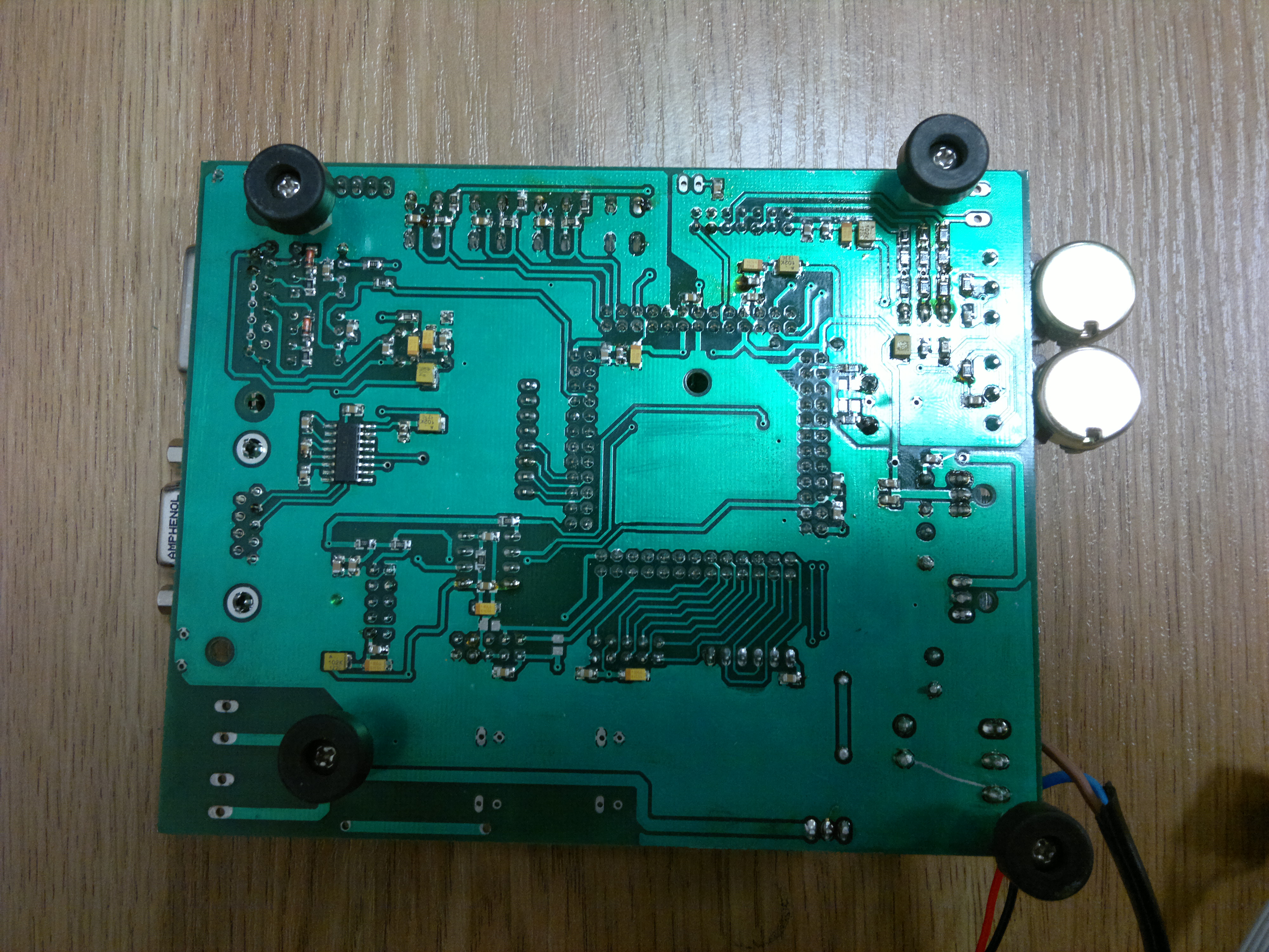
This picture shows the upper view of the control board made in photochemical method:
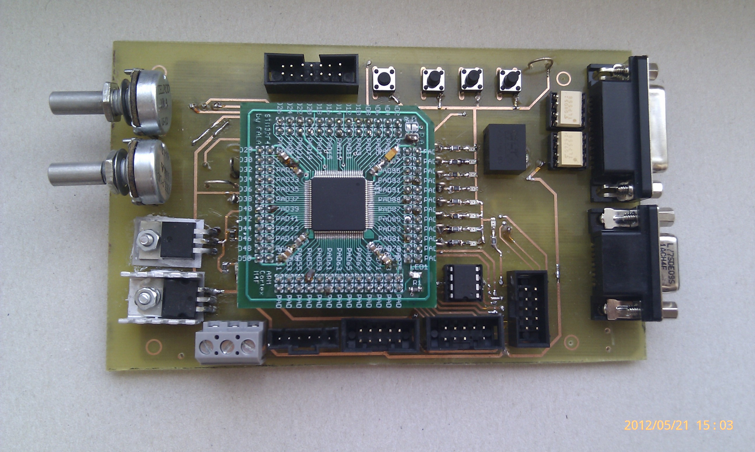
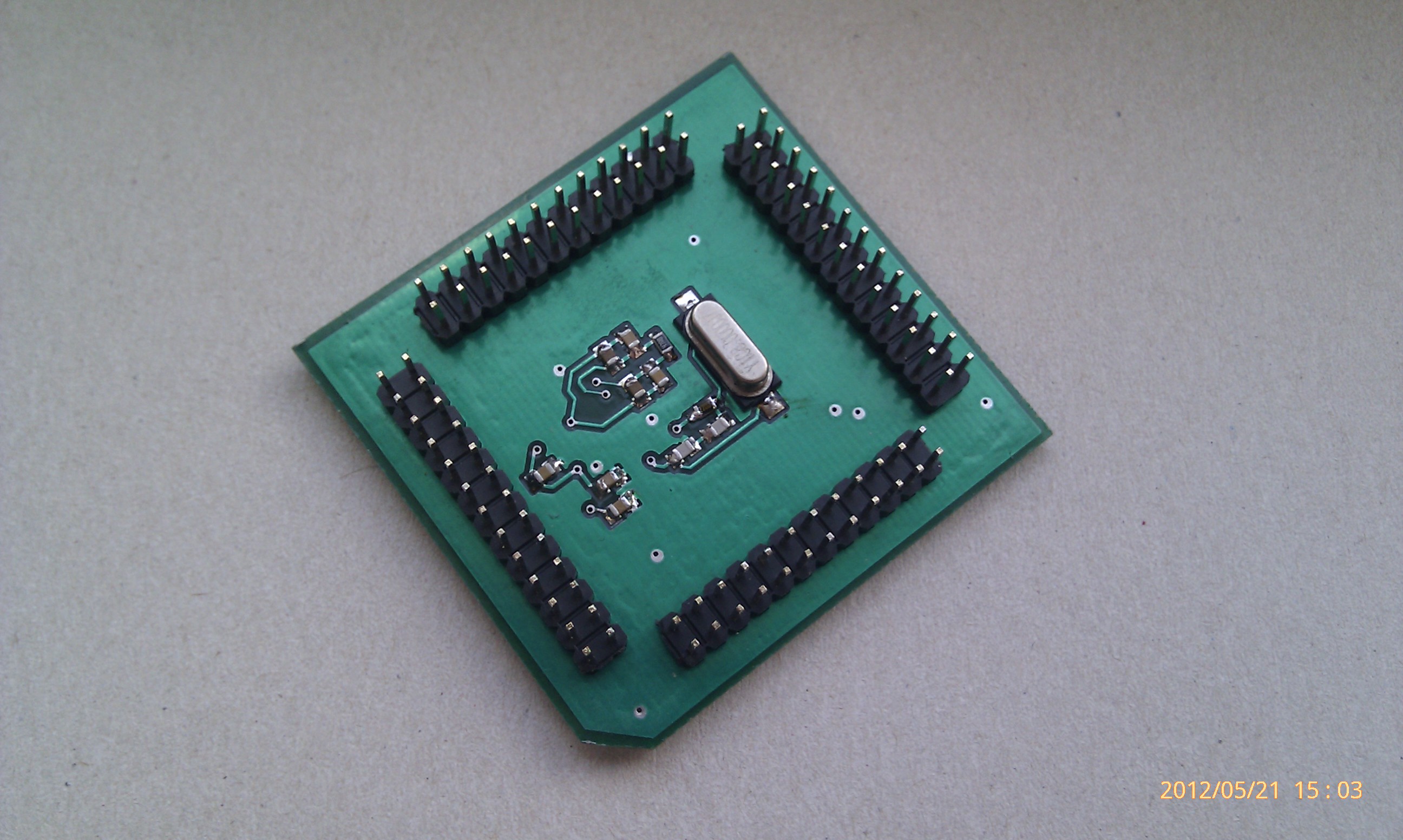
The first picture in this thread and the below picture show the control board made in a professional firm. It has additional peripherals that are not connected with described here project.
The heavy current part consisted of the fact that the circuit controlled the DC/AC converter, the main element of which was intelligent power module IPM PM15RSH120 from Mitsubishi. The inverter was powered from AC/DC converter (main converter), that allows for the adjustment of Udc voltage in intermediary circuit in scope of 600-750V. The main converter makes it possible for the system to test engine control in dynamic states.
The microcontroller implements the following actions:
- measure three phase currents
- measure the rotation speed or its sensor-less estimation, speed adjustment procedure
- estimation of magnetic flux on the basis of mathematical model of the induction engine
- current and flux transformations to stationary and rotating systems
- estimation of powering voltage Usaβ, synchronous pulsation and electromagnetic moment
- modulation function consistent with the DTC rule
- C/A converter handling
Results of laboratory tests:
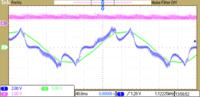
- for standard DTC method at high angular speed:
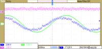
Phase current engine waveforms i_sU (Ch1) flux Ψ_U (C3) and the electromagnetic moment M (Ch4) (scale: i_sU – 2A/dz, Ψ_U- 0,5 Wb/dz, M – 4Nm/dz) at a speed ω_m 125rad/s
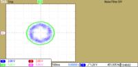
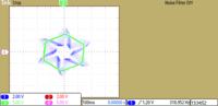
Hodographs of current vectors i_sαβ (Ch3) and flux Ψ_αβ (Ch1) in stationary coordinate system at a speed ω_m 125rad/s
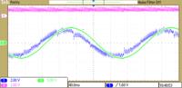
- for standard DTC method at low angular speed:
Phase current engine waveforms i_sU (Ch1), flux Ψ_U (Ch3) and the electromagnetic moment M(Ch4) (scale: i_sU – 2A/dz, Ψ_U- 0,5 Wb/dz, M – 4Nm/dz) at a speed ω_m 11rad/s
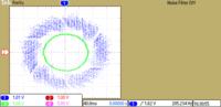
Hodographs of current vectors i_sαβ (Ch1) and flux Ψ_αβ (Ch3) in stationary coordinate system at a speed ω_m 11rad/s
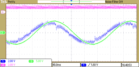
- for modified DTC method at low angular speed (at high angular speed, the results is similar to the standard method):
Phase current engine waveforms i_sU (Ch1), flux Ψ_U (Ch3) and the electromagnetic moment M(Ch4) (scale: i_sU – 2A/dz, Ψ_U- 0,5 Wb/dz, M – 4Nm/dz) at a speed ω_m 11rad/s
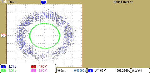
Hodographs of current vectors i_sαβ (Ch1) and flux Ψ_αβ (Ch3) in stationary coordinate system at a speed ω_m 11rad/s
Link to original thread (useful attachment) - Falownik napięcia na STM32F407