Vermes
Advanced Member level 4
This design is an AC/DC inverter based on dsPIC30f6010A. The circuit is intended to power an engine inverter which can be a drive inverter supplying the induction motor or DC/DC converter for the DC motor.
The most important features of the AC/DC inverter:
- current consumption of a waveform shape similar to sinusoidal and unity power factor
- two-way flow of energy
- regulation of the dc-link voltage
The unity power factor indicates that only the active power is taken from the mains, the currents are in phase with the corresponding voltages. Such a situation is the most advantageous in terms of supply network, because the reactive power causes the increase in the current value, and thus the transmission losses and the need to oversize electro-energetic equipment.
The microprocessor part was executed on the basis of signal microcontroller dsPIC30f6010A. Method of inverter control by current was implemented in the microcontroller. Due to the fact that in the algorithm, the values converted are the floating-point values, and the microcontroller is a fixed-point one, the time of executing it is much longer than the possible maximum. Because of that, there was used a method of representation of the floating-point numbers on the fixed-point microcontroller, which is scaling the variables values. That procedure allowed for the implementation of the algorithm in a surprisingly short period of time around 20us with giving the selected signals to the C/A converters.
Schematic diagram of the controlling part:
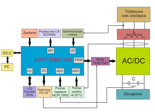
The most important components of the controlling part include:
- microcontroller dsPIC30f6010A
- current sensor ACS712
- voltage sensor HCPL7800
- system of synchronization with network
- digital-analog converters MPC4922
- LCD with buttons
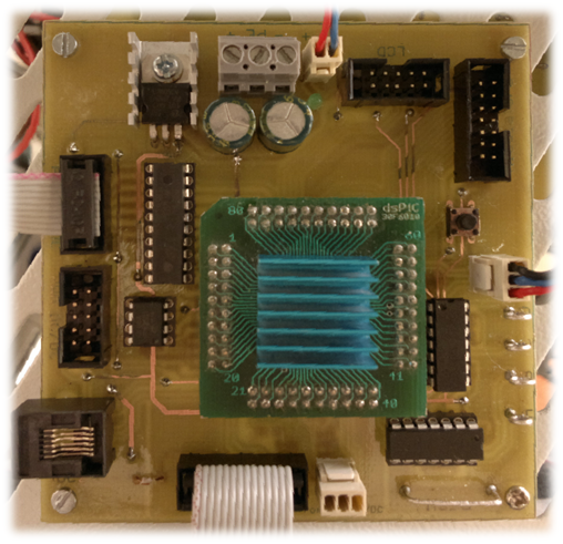
High current part consists of the following components:
- two-level intelligent power module (IPM) PM25RSB120 of a bridge typology ie 6 transistors and 6 diodes
- mains chokes of an inductance 20mH
- two filtering capacitors connected in series of a total capacity 1100uF
- two capacitors protecting against surges connected in series of a total capacity 1000uF
- resistors limiting the charging current in the phase of switching on the device
- resistors discharging the capacitors after disconnecting the device
- set of contactors and switches with a fuse
- block powering the processor and measuring parts
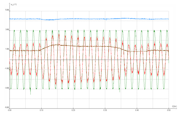
Results of tests:

The blue waveform presents the dc-link voltage Udc, the output voltage of the inverter, the brown waveform presents the phase voltage of the network supply, the red waveform is the phase current of the network, and the green waveform is the active power. Tested inverter was charged with an inverter motor, which allowed recording the dynamic states such as the return of energy to the supply network while the return of the motor.
This picture shows the step change in load. The waveform of the voltage shows the voltage in the Udc link circuit, the green waveform – phase voltage in the mains. The brown waveform – effective value of the set current, and the red waveform – the actual current.
Link to original thread - Przekształtnik sieciowy AC/DC na dsPIC30f6010A