Continue to Site

Welcome to EDAboard.com

Welcome to our site! EDAboard.com is an international Electronics Discussion Forum focused on EDA software, circuits, schematics, books, theory, papers, asic, pld, 8051, DSP, Network, RF, Analog Design, PCB, Service Manuals... and a whole lot more! To participate you need to register. Registration is free. Click here to register now.

visualizing linear polarization with cross and co pol in CST

Status
Not open for further replies.

yefj

Advanced Member level 4
Joined
Sep 12, 2019
Messages
1,195
Helped
1
Reputation
2
Reaction score
3
Trophy points
38
Activity points
7,217
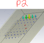
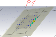
Hello,in the patch bellow i have two ports which creates individual electric fields orthogonal to each other as shown bellow.
I have tried to test the polarity of each field using co and cross polarization of some reference linear polarity
From all photos we can see the electric fields is pointed to the Z-direction.(but from different side).
so given the menual menu bellow:

So looking with respect to the Antenna what is Ludwig X=1 Z=1 polarization means?
How can i vissualy imagine this situation?
Thanks.
1626896715368.png

1626894532102.png

1626896255359.png

1626896100255.png
 

Attachments

  • 1626895108944.png
    1626895108944.png
    56.6 KB · Views: 96
  • 1626895160138.png
    1626895160138.png
    81 KB · Views: 93

You need to look at the radiated E-field at some distance from the antenna. The near field inside the antenna that you showed is not useful to see polarisation of radiated waves.
 

Hello Volker,In anechoic chamber the radiation of an antenna is govrned by the Polarizarion loss factor as shown bellow.
given the ludwig3 menu bellow where Z=1 and X=1, what is the pure vectoric definition value of L(reference antenna in the formula)?
Thanks.
1626924780312.png
1626923602221.png
 
Last edited:

Status
Not open for further replies.

Part and Inventory Search

Welcome to EDABoard.com

Sponsor

Back
Top