Continue to Site

Welcome to EDAboard.com

Welcome to our site! EDAboard.com is an international Electronics Discussion Forum focused on EDA software, circuits, schematics, books, theory, papers, asic, pld, 8051, DSP, Network, RF, Analog Design, PCB, Service Manuals... and a whole lot more! To participate you need to register. Registration is free. Click here to register now.

Vectrex PSU problems

Status
Not open for further replies.

neazoi

Advanced Member level 6
Joined
Jan 5, 2008
Messages
4,123
Helped
13
Reputation
26
Reaction score
15
Trophy points
1,318
Location
Greece
Activity points
36,955
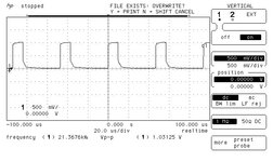
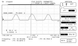
Hi I am fixing a Vectrex game console and I see the CRT filament is not glowing. I disconnected the CRT and fed power to the filaments from an external PSU and they do glow, so the CRT works. I traced back the problem and measured the output of the 555 (page 32 on the manual). The output image is attached.
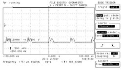
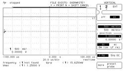
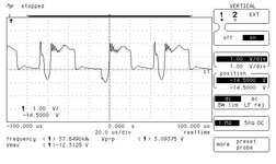
Then I measured the base and collector signals of the BU407 and they do not seem right.
I measured T501 primary and secondary with an ohms meter:
primary=4.4 ohms
Secondary=0.8 ohms

However when I connect the multimeter to one pin of the the primary and one of the secondary I get zero ohms.
I measure it in circuit.
What does it mean, is the transformer bad or is it shorted through some other path?
However I can still measure resistances in the pri/sec alone, so this does not make sense
 

Attachments

  • Vectrex-Service_Manual.pdf
    4.7 MB · Views: 94
  • pin 3 of 555.jpg
    pin 3 of 555.jpg
    48.8 KB · Views: 160
  • base of bu407.jpg
    base of bu407.jpg
    52.9 KB · Views: 140
  • collector of BU407.jpg
    collector of BU407.jpg
    49.2 KB · Views: 135

Probably the BU407 is faulty. If it is, you are lucky - it will have over 100V pulses on its collector so your scope would be dead by now!

Next guess would be C504 is open circuit.

Brian.
 

Probably the BU407 is faulty. If it is, you are lucky - it will have over 100V pulses on its collector so your scope would be dead by now!

Next guess would be C504 is open circuit.

Brian.
I will check C504 to see if I can get any pulses out of it.
The scope has 250V input at 1M (max), I do not think it will find any trouble, do you?
--- Updated ---

I will check C504 to see if I can get any pulses out of it.
The scope has 250V input at 1M (max), I do not think it will find any trouble, do you?
UPDATE I get pulses out of C504, it does not seem bad.
but why the transformer seems shorted in the pri/sec connections on the multimeter?
 
Last edited:

Hello neazoi,
There would be nothing wrong with Q502 (BU407), as you would be measuring R507 (4.7Ω) resistor in the circuit.
This is measuring between the base and emitter.
I also doubt that there would be anything wrong with T501. It is possible you could have shorted turns, but unlikely.
Try removing T501 from circuit, then remeasure it. If you find it OK, then you need to look elsewhere.
The filaments won't glow if the high voltage isn't working (flyback transformer (T502)).
Looks like you need to check voltages...
Please let us know how you get on.
By the way, what exactly is it's symptoms apart from the CRT not glowing?
Regards,
Relayer
Ok, the thing was working ok, but then some nice guy thought that it would be a brilliant idea to change some chips with ceramic versions, as well as the ROM with an EPROM. When fitted the EPROM, it was working ok, but when changed a few other logic chips it stopped working. It stopped doing the start up sound. At some point, (he does not remember if it was at the same time or afterwards), he noticed this screen problem as well (filaments not glowing).
The two problems may be un-related, so I am trying to find first the flyback problem, as indeed if there are no pulses in the primary, there will be no outputs at any of the secondaries, including the filaments.
So yes, before starting to desolder things, I thought it might be a good first approach to measure some components in circuit. BTW, there are +9 and -9v present, as well as -5,+5,+13,-12

I jsut think that if the transistor is shorted, It could lead to destroy of the flyback primary wouldn't it? However I do measure a contact between the primary pins, so it might have survived.
 
Last edited:

Probably the BU407 is faulty. If it is, you are lucky - it will have over 100V pulses on its collector so your scope would be dead by now!

Next guess would be C504 is open circuit.

Brian.
I desoldered the BU407D (Q502) and checked it on a components tester. The result is short in the checker.

I also soldered a BU508AF (from an old TV I happened to have) in place, as a quick test.
Now the filament works and I get these waveforms at it's base and collector. Note the scope values.

With about 3vpp at the base it produces 93vpp pulses at the collector.

I can hear a high pitch sound from the vectrex, it might be normal or it might be HV arcing? I can see no visible ark, but of course this is difficult to say. It might be the HF deflection I do not know. The volume is not high, but neither as low as I can remember on the old CRTs. I do not remember if the working vectrex had that sound, cause it's speaker has a lot of hum normally. Also, now I have the cabinet open, so it is heard a bit more.

I still see nothing on the screen but I can also hear no startup sound due to the faulty logic board.
Is it safe to leave this replacement transistor there for my tests, until I get the original one?
--- Updated ---

I desoldered the BU407D (Q502) and checked it on a components tester. The result is short in the checker.

I also soldered a BU508AF (from an old TV I happened to have) in place, as a quick test.
Now the filament works and I get these waveforms at it's base and collector. Note the scope values.

With about 3vpp at the base it produces 93vpp pulses at the collector.

I can hear a high pitch sound from the vectrex, it might be normal or it might be HV arcing? I can see no visible ark, but of course this is difficult to say. It might be the HF deflection I do not know. The volume is not high, but neither as low as I can remember on the old CRTs. I do not remember if the working vectrex had that sound, cause it's speaker has a lot of hum normally. Also, now I have the cabinet open, so it is heard a bit more.

I still see nothing on the screen but I can also hear no startup sound due to the faulty logic board.
Is it safe to leave this replacement transistor there for my tests, until I get the original one?
As far as concern the logic board, I get no clock signal if I connect the scope to each pin of the crystal of the cpu. What does this mean?
 

Attachments

  • base.jpg
    base.jpg
    49.3 KB · Views: 142
  • collector.jpg
    collector.jpg
    53.2 KB · Views: 113
Last edited:

The BU508 is fine for testing.
I have some BU406D transistors here if you need them. They are identical to the BU407 but have a higher VCE rating.

The scan and HV seems to be working so you now need to concentrate on the logic board. If it doesn't initialize you will never get any sound or video.

Brian.
 

    neazoi

    Points: 2
    Helpful Answer Positive Rating
The BU508 is fine for testing.
I have some BU406D transistors here if you need them. They are identical to the BU407 but have a higher VCE rating.

The scan and HV seems to be working so you now need to concentrate on the logic board. If it doesn't initialize you will never get any sound or video.

Brian.
I can find these transistors locally, cheap. But thank you very much for your kind offer anyway!
The fact that I can get no clock when I connect the scope probe to any of the crystal pins puzzles me. It means the board does not initialize.
I tried another CPU (the B version which is of faster speed) and yet I cannot measure any signal on the crystal pins.
I checked the voltages at the connector of the board and they are fine +5v -5v -13v. Initially the 7805 regulator gave 4.81v and I changed this to a modern one and now it is at 5.05v. It might not matter a lot, but I thought it to be a good idea since the lower VCC of the cpu is 4.7v.

I am going to have a closer look at the logic board and especially around the CPU, and come back to you.
My guess is that, even with no other chip fitted on the board, the CPU should initialize and show a clock on the crystal pins, unless VCC is absent.
 

The clock should run regardless of any other circuitry so get that working first.
Use x10 probes on the crystal, otherwise the probes themselves may stop it oscillating.
Note that with the exception of the 555 you have already conformed is working, there are no other clock sources in the machine. This means if you see activity on the other pins, even if the crystal appears to be dead, it is almost certainly running.

Brian.
 

    neazoi

    Points: 2
    Helpful Answer Positive Rating
The clock should run regardless of any other circuitry so get that working first.
Use x10 probes on the crystal, otherwise the probes themselves may stop it oscillating.
Note that with the exception of the 555 you have already conformed is working, there are no other clock sources in the machine. This means if you see activity on the other pins, even if the crystal appears to be dead, it is almost certainly running.

Brian.
I put the 10x scope probe to each of the pins of the CPU and I get no clock or pulsed signal at any of them. I only get 0v or 5v or some voltages in between, but always DC. I tried different horizontal scope settings. On changing the CPU to 68B09 instead of 68A09, I notice a steady 5v DC on one of the cryatal pins, whereas with the A version I sense almost no DC.
I checked the CPU socket pins and near-by pins are not shorted.
I also changed the crystal to another one, but no luck.
Maybe the cpu is somehow held i reset state? But should I be able to detect any clock then?
 
Last edited:

I'm not an expert with 68x processors but from the data sheet it looks like the clock should run all the time, regardless of the reset line. It would be unusual for the clock to stop when any processor is in reset state because of the relatively long time it takes (mS) for the oscillator to stabilize. Finding 0V or 5V on one of the oscillator pins may be normal as inside the IC there is an inverter between them but normally when oscillating the level will only swing between high and low logic thresholds rather than full logic levels.

It seems there is still some problem around the crystal. Worth noting that DC shifts around the crystal could stop it so check for any contamination on the PCB in that area that might be leaking some current into the circuit.

Brian.
 

    neazoi

    Points: 2
    Helpful Answer Positive Rating
Hi,

Seeing DC (close to VCC or GND) on an XTAL surely means it is stopped.
The problem is: even a scope probe (with it's impedance) is able to stop an XTAL oscillator.
Thus it's more informative to measure the oscillator OUT than the IN, because it is less sensitive on load.

If the oscillator input is stopped by some leakage current on the IN node (dirt, humidity, internal currents, flux residuals...) then a 1M across the XTAL may help to start oscillation.
Also you may replace the capacitors.

Klaus
I tried 1M across the crystal but no luck
Mine had 10uF 16v tantalum at c228 instead of 22uF shown in the manual. I changed that to 22uF 16v aluminium, thinking that it might interfere with the reset line, but no luck again.
I cleaned all the residual flux from the PCB, but no luck.
I also put the scope probe on the J301, but I see no pulses there. I just see +340mv on the Z-axis and -3.4v on the X and Y axes.

I start to run out of ideas...
 

Again, looking at the data sheet, if -RES is above 4.0V (note this is higher than normal logic 1 threshold) there should be activity on the other pins, even if it is just searching for instructions. It is pulled high through R201 with C224 and C228 delaying it's rise at power-on. If it is lower than 4V check the component on the reset line and reset switch. Note that the reset pin on the sound generator IC is an input so it shouldn't be able to drive the reset signal.

Brian.
 

    neazoi

    Points: 2
    Helpful Answer Positive Rating
Again, looking at the data sheet, if -RES is above 4.0V (note this is higher than normal logic 1 threshold) there should be activity on the other pins, even if it is just searching for instructions. It is pulled high through R201 with C224 and C228 delaying it's rise at power-on. If it is lower than 4V check the component on the reset line and reset switch. Note that the reset pin on the sound generator IC is an input so it shouldn't be able to drive the reset signal.

Brian.
RST pin 37 on the CPU is high +5V.
Just as an experiment I also tried a 2200uF for c228, to delay the RST line (just a thought) but noo luck.
I see no pulsed activity on the CPU pins. Would it help if I provide you the voltages I measure on them?
 

Hi,

what´s the exact part number of both ICs?

they may end with -P or -EP or else (While the -EP is likely not to work with your circuit, because it is not designed for XTALs)

Klaus
 

    neazoi

    Points: 2
    Helpful Answer Positive Rating
Hi,

what´s the exact part number of both ICs?

they may end with -P or -EP or else (While the -EP is likely not to work with your circuit, because it is not designed for XTALs)

Klaus
Thanks for that info.
The original CPU was HD68A09P
After ruining it (cut pins and desoldered it), I replaced it with EF68A09P
Since there is a CPU socket now, I have also tried MC68B09ES as well as MC68B09S
I have now fitted the EF68A09P to do the measurements mentioned above.
 

Attachments

  • EF68A09P.pdf
    1.1 MB · Views: 80
  • HD68A09.pdf
    2.1 MB · Views: 65

Hi,

so,
* Don´t use one with an "E" in the suffix.
* MC68A09 and MC68B09 should work(speed), but MC6809 may not work with 6MHz.
"C" means extendend temperature range (does not matter)
"P" means plastic package (does not matter)
"S" means ceramic package (does not matter)

So after power ON I´d check (in this order)
* power supply voltage
* reset level
* XTAL activity
(I think this is as you did)

Klaus
I fixed it! :)

I have tried the MC68B09S before as I told you, but I never pushed it far into the socket (not to bend the pins)
Now tried that and the thing worked!
I still do not know why the EF68A09P did not work. It seems the vectrex is picky on the CPU.
By the way, the flyback driver transistor I replaced (different type than the original, similar specs) works fine.

Thanks for all the help, I have learn a lot in debugging this thing.
 
Status
Not open for further replies.

Similar threads

Part and Inventory Search

Welcome to EDABoard.com

Sponsor

Back
Top