Continue to Site

Welcome to EDAboard.com

Welcome to our site! EDAboard.com is an international Electronics Discussion Forum focused on EDA software, circuits, schematics, books, theory, papers, asic, pld, 8051, DSP, Network, RF, Analog Design, PCB, Service Manuals... and a whole lot more! To participate you need to register. Registration is free. Click here to register now.

using iphone charger as power source up to 1A

Status
Not open for further replies.

stanislavb

Full Member level 2
Joined
Jun 8, 2008
Messages
121
Helped
2
Reputation
4
Reaction score
2
Trophy points
1,298
Activity points
2,067
Hi,
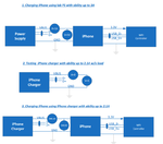
Does any body know how to use iphone charger as PS supply with ability provide 1A.
Currently it provides not more than 300mA only. However charger specification is 1.5A...
Thank you
 

Hi,

Usually a iPhone charger is a 5V power supply with DCP standard.

How did you test? Circuit, currents, voltages..

Read about USB charging ports.
Wikipedia has some informations,
And/or look at usb.org

Klaus
 

Hi
It written 0.15A on 220V. Pay attention what written about 5V rail. I measured current on 5V and got 300mA only. For fast charging iPhone charger can provide 1A for iPhone and even more(I don't remeber how much) for iPad
Thank you

- - - Updated - - -

Hi,
I measured maximum current iPhone charger provides to load. Once I exceed this value the voltage is dropping down.
How I know iPhone charger is using D+/D- lanes to configure iphone device "to take" up to 1A. I was convinced that iPhone charger provides it's maximum current every time. However after number of experiments I am feeling that this is not reality: it gives not more than 300mA. May be I have to use D+/D- lanes to provide to iPhone charger any additional information?
Thank you
 

Hi,

AGAIN: How did you test? Circuit, currents, voltages..

Klaus
 

Hi,

AGAIN: How did you test? Circuit, currents, voltages..

Klaus
The experiments slightly complicated.
Attached file describes experiments has been done. Below some comments.
I choose iPhone charger with ability 2.1A.
MFI controller - controller which using MFI commands to permits iPhone draws charging current 1A. As you can see in first experiment using lab PS I succeed to charge Iphone with current 1A. To provide power for controller I used battery power from iPhone. However it is not necessary: I could to draw power for MFI controller using external PS.
The second experiment only shows that w/o load iPhone charger supplies 5V.
Of course I could to connect iPhone charger to static load to simplify setup. However my final configuration will be similar as for experiment 3. So I prefer to understand what's wrong in my setup or what I need in additional to draw current 1A.

Thank you
 

Attachments

  • Experiments.png
    Experiments.png
    54 KB · Views: 113

Hi,

in your experiment it seems the D+ and D- are not connected to the charger.
But for high current charging they need to be connected to show each other´s capabilities.

Especially the "4.6V, 0.3A" shows, that the carger does not supply enough current.
(I hope your wires and current measurement is low ohmic enough)

Did you read: https://discussions.apple.com/docs/DOC-3511

Klaus

Yes I am feeling the same. Once in some paper I found that connecting voltage divider to D+/D- lanes will configure system to use charging current 1A . I connected this dividers to D+/D- lanes of iPhone charger but did not achieve willing result. Also I found simplifying schematics of Ipone charger and found these dividers inside. So there are no needs for externals resistors. Moreover I did not find any more connection D+/D- lanes inside iPhone charger. In other word D+/D- bias doesn't affect on current ability of the iPhone charger(or may be exists any secret mechanism, which was not shown in schematics...). So situation even more strange than I though...
 

Hi,

Wikipedia:

https://en.wikipedia.org/wiki/USB

Especially read "USB charging" chapter.

Also interesting chapters "cabling", "power", "USB Power Delivery (UPD)"

klaus

Well I reviewed it and even BC1.2 . What I can not understand is that all paper which describing charging process, states that portable device(not charger!) should detect charger, charging port, maximum charging current and etc. But I never heard that charger uses D+/D- lane for any identification, enable and etc. From BC1.2 it seen that if I'll emulate aside charger on D+/D- lanes it will be enough. Moreover with regular PS this is working! However iPhone charger needs something more. And I don't understand what...From other side if I connect charger to iPhone right away I'll not able to use USB lanes for data transfer. You wrote the iPhone charger support DCP: this mode intends not using D+/D- lane during charging.
In case charger also needs any indication through D+/D- lane it was ideally to emulate it in anyway aside, but not connect to D+/D- of a iPhone itself.
Thank you
 

Hi,

There is a power supply (5V. I avoid to call it "charger", because it simply is a power supply) and the iphone.
Inside the iphone there is the charging circuit (I rather call this a "charger").
The charging circuit inside the iPhone controls the charging current.

Because there are several USB style power supplies... the supply must "communicate" its max. current capability to the iphone.
This is done with the D+ and D- lines.
Means: there must be a D+ and D- connection between iphone and power supply. (this is missing in your circuit)

from Wikipedia:
Before the battery charging specification was defined, there was no standardized way for the portable device to inquire how much current was available. For example, Apple's iPod and iPhone chargers indicate the available current by voltages on the D− and D+ lines. When D+ = D− = 2.0 V, the device may pull up to 500 mA. When D+ = 2.0 V and D− = 2.8 V, the device may pull up to 1 A of current.[98] When D+ = 2.8 V and D− = 2.0 V, the device may pull up to 2 A of current.[99]

-> the power supply controls the D+ and the D- voltage.

Mind that there are several max current "communication" standards.

Klaus
 

Hi,

There is a power supply (5V. I avoid to call it "charger", because it simply is a power supply) and the iphone.
Inside the iphone there is the charging circuit (I rather call this a "charger").
The charging circuit inside the iPhone controls the charging current.

Because there are several USB style power supplies... the supply must "communicate" its max. current capability to the iphone.
This is done with the D+ and D- lines.
Means: there must be a D+ and D- connection between iphone and power supply. (this is missing in your circuit)
from Wikipedia:
Before the battery charging specification was defined, there was no standardized way for the portable device to inquire how much current was available. For example, Apple's iPod and iPhone chargers indicate the available current by voltages on the D− and D+ lines. When D+ = D− = 2.0 V, the device may pull up to 500 mA. When D+ = 2.0 V and D− = 2.8 V, the device may pull up to 1 A of current.[98] When D+ = 2.8 V and D− = 2.0 V, the device may pull up to 2 A of current.[99]

-> the power supply controls the D+ and the D- voltage.

Mind that there are several max current "communication" standards.

Klaus


Yes, you quite right. Of course power supply controls the D+ and D- . This is a reason instead define different voltage between D+ and D- lanes I am using MFI controller sending MFI command to iPhone to define max current. In case with simple power supply it works! The external power supply is ready to supply any current iPhone configured to. But in case with iPhone charger not. May be in one side iPhone charger puts resistor dividers on D+/D- lanes to point out to iPhone permitted charge current ;from other side iPhone charger has current limiter which has any relation with these resisitor dividers. However I built additional experiment similar as experiment 3 but D+ and D- lanes of iPhone charger connected to recommended divider to achieve voltages on D+ and D- lanes related to 1A(however D+/D- still was not connected to USB_D+/USB_D- lanes). The result I got was the same: only 300mA...
Thank you
 

Status
Not open for further replies.

Part and Inventory Search

Welcome to EDABoard.com

Sponsor

Back
Top