Continue to Site

Welcome to EDAboard.com

Welcome to our site! EDAboard.com is an international Electronics Discussion Forum focused on EDA software, circuits, schematics, books, theory, papers, asic, pld, 8051, DSP, Network, RF, Analog Design, PCB, Service Manuals... and a whole lot more! To participate you need to register. Registration is free. Click here to register now.

USB Controlled CNC for PCB drilling.

Status
Not open for further replies.

Yosmany325

Member level 3
Member level 3
Joined
Oct 31, 2012
Messages
62
Helped
8
Reputation
16
Reaction score
8
Trophy points
1,298
Activity points
1,758
Hi everybody. Some time ago I started to design/develop an USB controlled CNC machine, intended mainly for PCB drilling. In this post I'm trying to show my work until now. The attachment contains a PDF file with the schematics of control board, based on PIC18F4550 from Microchip and also a ZIP file with gerbers of PCB for this controller part. This board is intended to be connected to some auxiliar boards, containing stepper motor drivers, spindle control board and sensor boards. The sensors are for Start and End of each axis and are read using an analog input (i.e. reading the voltage at each analog input I detect which axis(axes) are at Home positions/End positions. Any comments regarding this work are welcome. Right now I'm working in the development of stepper control board, based on SLA7024M chip (I use this chip because at have it at hand right now). Also I'm working in the source code for PIC.

Sooner I will publish my advances. Thanks for your time to read this. Yosmany325.
 

Attachments

  • ControlBoard.zip
    91.9 KB · Views: 246

Hello, recently I have finished the PCB design for stepper motor driver boards. The design should use 3 of them, one for each axis. As I stated before, the driver boards are based on SLA7024M chip, but this can be changed by the superior current capable SLA7026M. I hope this time anyone can post any comments about the PCB, i.e. if contains errors or something that can be enhanced. Thanks in advance.
 

Attachments

  • StepperBoard.zip
    73.6 KB · Views: 236

hi dear, you can post some images here, it maybe there will be noone download the file. of course, it's just an advice.:wink:
 

Hello. I have recently finished the PCBs although I have not mounted the components. Right now I'm choosing the spindle motor. The idea is to use an RC motor like A2212/13T of KV1000. The main issue I'm facing right now is the motor controller. Later I will post the pictures of PCB. Best regards Yosmany325.
 

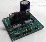
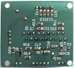
Hi everyone, I just finished the mounting of the components of the stepper driver board. In the attached pictures can be seen the result. Any advice or comment will be welcome. Thanks in advance.

FrontPCBStepper.jpg
BottomPCBStepper.jpg
 

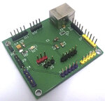
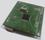
Hello, this weekend I finished the mounting of the two remaining stepper motor driver boards. Also I finished the controller board. In the pictures shown is the end result. The most hard part was the mounting of the PIC microcontroller, but after some effort it is done. Yosmany325.

TopCtrlBrd.jpgBottomCtrlBrd.jpg
 

Hello,

It's all right for hardware. But here most & most impotent task is software for controlling the motors in a precision work in +- 0.001mm. Second is communication. May be i think that you will send NC file data by PC threw USB port.


Related controlling subjects

1. Bad Limit controlling.
2. Reference.
3. 3 axis control.
4. Program pause/Resume at power fail time.
5. Save working coordinates in external memory.

If i was place of you will never think for drive. I think for my software performance only and exemption to errors during operation my machine. However you are making a drive also...It's so cool.

- - - Updated - - -

I am interested in CNC controlling devices. We can a lot of discuss on it.
 

Status
Not open for further replies.

Similar threads

Part and Inventory Search

Welcome to EDABoard.com

Sponsor

Back
Top