Gaber Mohamed Boraey
Full Member level 2
Hello everyone
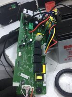
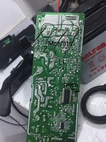
While I repair 700 watt ups I find shorted micro controller number Hr7p195fgs3
Datasheet here
I mean with shorted “ have short circuit “ , I discovered that with voltage injection, as had 5v should be there written on pcb and when work only 1.2v , so I objected 5v and found high temperature at the controller, I’ve changed with same number from similar board, “ as we have big stock”, but not same board, and it worked fine and solved the problem
For ups check I had to measure the output with true rms Fluke Multimeter, and the reading is about 245v “ high for ups “? , right? , I thought something wrong in the board and put new board instead and the output is 230v, i had same device i checked its output and its 550vac
How you think?, bad ups board and design?
when measure frequencies at the mosfets low side and high side, pwm frequency is 50hz at two mosfets and 100hz at two others , I thought always that’s frequencies at mosfets should be Same, can anyone explain to me the switching in ups?
The output is modified squares wave by the way, not sine wave signal
Attachments
Last edited: