Continue to Site

Welcome to EDAboard.com

Welcome to our site! EDAboard.com is an international Electronics Discussion Forum focused on EDA software, circuits, schematics, books, theory, papers, asic, pld, 8051, DSP, Network, RF, Analog Design, PCB, Service Manuals... and a whole lot more! To participate you need to register. Registration is free. Click here to register now.

400 watt smps repair

Gaber Mohamed Boraey

Full Member level 2
Joined
Feb 26, 2015
Messages
149
Helped
4
Reputation
10
Reaction score
10
Trophy points
1,298
Activity points
2,249
Hello everyone

I have that power supply
01146B85-C75A-41A0-AC86-D920C0D2C0B3.jpeg

With shorted mosfet, and I decided to install power module because the mosfet not available in local market

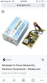
There are many universal power module available in market, with different power capacities


200 watt universal power module , which is high power , here is detail about it


Also attached photos

My power supply is 12v, 400 watt

A31A19F6-CE03-4010-BACF-CB01F5D78A8E.jpeg


Can I use that universal power module here safely?, will it handle the power supply load?, is there anyway we can know if it’s safe to use or know at loads?
--- Updated ---

Here is another module for more specifications, they say it’s 300 watt and handle 3 amp load


Attachments

  • A67F9A66-9FAA-455A-A4EB-6D88E140D4CF.png
    A67F9A66-9FAA-455A-A4EB-6D88E140D4CF.png
    621.5 KB · Views: 47
Last edited:
I doubt if your suggest 3A replacement can replace a 33A 12V supply with a fan.

Try a 500W PC PSU supply which might easily supply 33A @ 12V
maybe even an old 350W supply might be enough.

Cooling is critical to reliability and also routine dust removal yearly. Try not to put on floor where dust settles.
 
Try a 500W PC PSU supply which might easily supply 33A @ 12V
no need to use pc power supply, i need repair this one

how you think if i compare the mosfet specification of my power supply and the universal power supply to see ampere handling, and then decide or know?
 
Comparing MOSFETS in different circuits is pointless, each design has its own specification and rating requirements.

Isn't there a part number on the damaged MOSFET? gently bend its legs backwards so you can see the top (plastic) side of the package and send us a photograph of the markings on it. We might be able to find a direct replacement or suggest an alternative.

Brian.
 
I have little hope it will work. Allow me to explain.

When a power supply is rated at 400W @ 12 V that means 33A max
When a switch is rated at 300W from 5 to 24V, it is not inclusive of 12V but rather maximum at 24V
This means the max current (if it doesn't melt the plastic from losses) is 300/24V = 12.5A which is the limiting factor for heat rise in an open board convection cooled. That is going to be reduced by the ambient rise inside the case from self-heating.

Even with the old one which needed a fan to be cooled your only hope is to swap FETs and improve the heat conduction of the FET with heatsink compound and hope the fan still works with all the dust and corrosion on bearings. They will both be rated for > 300V and the 1st one more than likely failed from inadequate cooling and thermal runaway, a characteristic where the FET RdsOn rises with temperature when operating near it's thermal limit in a design that is constant current or under a constant load.


So go ahead and swap it and good luck keeping it cool. You can improve heatsink significantly and maybe it will work.
 
Isn't there a part number on the damaged MOSFET?
There is , but I hope the power module can work instead
52A11DF1-270B-4A21-B409-EE7AD1F094A2.jpeg

--- Updated ---

So go ahead and swap it and good luck keeping it cool. You can improve heatsink significantly and maybe it will work.
The old mosfet is 12A Maximum , I think it’s within same range as you calculated , so why not?

The power rating for primary side transformer is different than the secondary side loading
 
Its a 650V, 12A rated standard MOSFET and easily available from many sources. We have no idea where your 'local market' is, my nearest component supplier is over 100Km away so I have to order everything by mail. If you don't trust your local market to supply a MOSFET, do you trust them to supply a complete power supply which could have the same fake parts in it and have exaggerated ratings?

Brian.
 
This FET has specs:
VDS 650 V
RDS(ON)TYP 290 mΩ

If the transformer ratio is 300V/25V = 12 then current ratio of 3A would be 0.25A primary average with some peak based on Avg/d.f then heat rise will not be as much as I anticipated, so I will revise my speculation to suggest it may work.

Note the product photo shows the new FET with surface markings sanded off.
(IP security by obfuscation)
 
Its a 650V, 12A rated standard MOSFET and easily available from many sources. We have no idea where your 'local market' is, my nearest component supplier is over 100Km away so I have to order everything by mail. If you don't trust your local market to supply a MOSFET, do you trust them to supply a complete power supply which could have the same fake parts in it and have exaggerated ratings?

Brian.
Humm, I just tried the power module before and irk fine, and tried the mosfets and they are fake , that’s why i look for different way
--- Updated ---

If the transformer ratio is 300V/25V = 12 then current ratio of 3A would be 0.25A primary average with some peak based on Avg/d.f then heat rise will not be as much as I anticipated,
Good, Can you explain how calculate the ampere?, current ratio for transformer?, just clarify the Calculations please
 
Last edited:
Good, Can you explain how calculate the ampere?, current ratio for transformer?, just clarify the Calculations please

usual power in=out method neglecting losses for rough estimate

Vi/Vo=Ii/Io

Give the PSU a good cleaning with isoprop with old toothbruth. and well warm-air dried.

keep in mind the e-cap outlived the FET which may mean they under-designed the heatsink for the FET unless, thermal paste or the dust and humidity was a factor. You may need an electrical insulator and insulated screw to mount to case.
 
Last edited:
usual power in=out method neglecting losses for rough estimate

Vi/Vo=Ii/Io

Give the PSU a good cleaning with isoprop with old toothbruth. and well warm-air dried.

keep in mind the e-cap outlived the FET which may mean they under-designed the heatsink for the FET unless, thermal paste or the dust and humidity was a factor. You may need an electrical insulator and insulated screw to mount to case.
Okay, thanks , clear now, how you think of this module?, lower power?
17A17FB0-94FF-4BB1-A8BB-F353FD5A9D94.png
 
Last edited:
Tell us the p/n of the new FET in this exchange.
It must also be in the 250 mOhm range. and rated for Vds>=600V and will need good heatsink grease perhaps with insulator and with force air cooling to case.

It all depends on the efficiency losses maybe 10% of rated load and cooling capacity for a decent Rja. Perhaps with force air cooling this capacity rating may be increased.

- Power : up to 180W
 

LaTeX Commands Quick-Menu:

Similar threads

Part and Inventory Search

Welcome to EDABoard.com

Sponsor

Back
Top