Continue to Site

Welcome to EDAboard.com

Welcome to our site! EDAboard.com is an international Electronics Discussion Forum focused on EDA software, circuits, schematics, books, theory, papers, asic, pld, 8051, DSP, Network, RF, Analog Design, PCB, Service Manuals... and a whole lot more! To participate you need to register. Registration is free. Click here to register now.

[SOLVED] unstable MESFET amplifier

Status
Not open for further replies.

afz23

Full Member level 3
Joined
Nov 30, 2007
Messages
183
Helped
15
Reputation
30
Reaction score
14
Trophy points
1,298
Location
Bangalore
Activity points
2,758
I used CFY25 Infeneon device to design(simulation) an amplifier at 12 GHz and achieved 8dB gain
and acceptable return losses in design bandwidth.

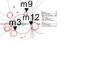
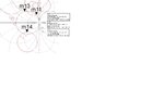
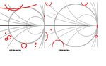
But there is a problem!!! the design shows instabilities K<1,near 4.5GHz and 7GHz.

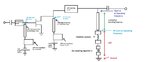
I tried to stablize the design ,using shunt and series stablizing resistors at output and input
side,but didn't succeeded,as these stablizing circuits are eating up all the gain at 12 GHz.

Seasoned designers say,not to worry about these instabilities,go ahead and fabricate as
practically amplifier will not see those loads which is leading to oscillations,as this impedance lies
at the edge of the smith chart in right hand side(high impedance area).

Experts please comment on this!!!!
 

If you have put the Input and Output Stability Circles here, I could say something more.
K<1 doesn't mean that the amplifier will absolutely oscillate ( but it may!!).
If you want to be sure about the stability, there are some techniques such as connecting a resistor at the drain or gate,small amount of negative feedback,emitter regeneration etc. to stabilize the amplifiers.
But cases are variable so you should find the right solution for your case.
 
Last edited:

If you have put the Input and Output Stability Circles here, I could say something more.
K<1 doesn't mean that the amplifier will absolutely oscillate ( but it may!!).
Hi BigBoss ,I am attaching the stability circles for your reference and further suggestions,thanks!!!

left one is i/p stability circles,right one is o/p stability circles
 

Attachments

  • ip stability.JPG
    ip stability.JPG
    75.1 KB · Views: 66
  • op stability.JPG
    op stability.JPG
    67.2 KB · Views: 59

Hi BigBoss ,I am attaching the stability circles for your reference and further suggestions,thanks!!!

left one is i/p stability circles,right one is o/p stability circles
As you see, some regions seem to be unstable for certain source/load combinations for both input and output.
My interpretation is that your amplifier will not oscillate since it's been loaded and sourced for moderate values of source and load.Because unstable regions are close to edge (extreme points) of the Smith Chart and since you don't use these impedances at both input and output, the amplifier will not oscillate.But in order to be sure, add a 400-800 Ohm resistor at the output with a blocking capacitor and re-try the simulation.You will possibly get that all circles will be outside of the chart.
 
Last edited:

    V

    Points: 2
    Helpful Answer Positive Rating
the amplifier will not oscillate.But in order to be sure, add a 400-800 Ohm resistor at the output with a blocking capacitor and re-try the simulation.You will possibly get that all circles will be outside of the
chart.

I understand ,why you are suggesting these values to be added at the output side?you don't want to show very high impedences at the output of the amplifier,as that may lead to oscillations as per the plotted. o/p stability circles.If I add say 400 ohms in shunt,,any higher value impedance appearing at the load will be ruled out,as any two impedences added in parallel,results in a value closer to the lower value.

Similarly,if I had a situation,where small impedences may lead to oscillations,,I would have added a value in series,so that amplifier always see impedences higher than the value added,and avoid oscillations.

Do these techniques,really work practically?I have seen them failing in simulation itself.

These resistors will be connected to the output in Parallel, not series..
Don't forget a decoupling capacitor.Use an ideal one for simulations..
 

Dear BigBoss, I have a doubt here.
The stability circuit should not effect the operating frequency performance,so designers
use λ/4 line to make the circuit open at operating frequency as shown in figure.
This makes stability circuit effective on other frequencies only.

But the electrical lengths of resistor, capacitor and solder pads (L≠0) makes the λ/4
line much longer and ineffective.

Please share your expertise to solve this design issue.

- - - Updated - - -

The figure.
 

Attachments

  • stability circuit.jpg
    stability circuit.jpg
    46 KB · Views: 59
  • stability circuit.jpg
    stability circuit.jpg
    46 KB · Views: 55
Last edited:

Dear BigBoss, I have a doubt here.
The stability circuit should not effect the operating frequency performance,so designers
use λ/4 line to make the circuit open at operating frequency as shown in figure.
This makes stability circuit effective on other frequencies only.

But the electrical lengths of resistor, capacitor and solder pads (L≠0) makes the λ/4
line much longer and ineffective.

Please share your expertise to solve this design issue.

- - - Updated - - -

The figure.
You did a mistake..
Lambda/4 circuit shows a Open Circuit when look at through the input of this line, so Line Input must be Open Circuit, Vdd line must be Short Circuit on your figure.You did it inverse..( I presume that upper line is Vdd )

Electrical lengths of resistor and capacitor pads are negligible since the operating frequency is not very high but they can also be taken into account of course.In this case, you should do a EM simulation to extract the effects of these parasitic components and you have to make an optimization as well.
 

Attachments

  • OutputCircuit.png
    OutputCircuit.png
    87.8 KB · Views: 57
Last edited:
  • Like
Reactions: afz23

    afz23

    Points: 2
    Helpful Answer Positive Rating
You did a mistake..
Lambda/4 circuit shows a Open Circuit when look at through the input of this line, so Line Input must be Open Circuit, Vdd line must be Short Circuit on your figure.You did it inverse..( I presume that upper line is Vdd )

Dear BigBoss, I am attaching the complete scheme for your reference,

As you can see, I am using traditional bias isolation circuit(combination of high and low QWL(quarter wave lines)) to
make the circuit open for RF at bias points,but dc short.

Similarly ,I want to make the stability circuit open at operating RF frequency,so that required RF power doesnot flow in
the stability circuit and lost ,but other frequencies will be effected by the bias circuits,as the line is not QWL for all
the frequencies.

I can adjust the length of the λ/4 line in simulation,so that it effects the unstablising frequencies but not the center frequency 12GHz.

- - - Updated - - -

Please quote me ,if I am wrong,thanks for your help and expert comments.
 

Attachments

  • circuit scheme.jpg
    circuit scheme.jpg
    88.7 KB · Views: 54

Please quote me ,if I am wrong,thanks for your help and expert comments.
Since you use Stabilizing Resistor just after the Lambda/4 TL, it's not possible to obtain a "Open Circuit" at its input and in this case Stabilizing Resistor will NOT serve anything.
Stabilizing can nor be done for specific particular frequency, instead it should be done for all operating bandwidth and even beyond.
Your configuration is not appropriate, please use what I have drawn.
 
  • Like
Reactions: afz23

    afz23

    Points: 2
    Helpful Answer Positive Rating
Thanks, I could understand what you said.whether de-coupling
capacitor shown in your circuit makes any difference,if used
after the resistor rather than before it.

- - - Updated - - -

I did what you said.It did helped in stabilizing at most
frequencies,,except 4.5Ghz.
 

I tried again,with actual pad sizes of resistor and capacitor.It got stabilized(see figure),But the gain of the amplifier
came down by few dBs,need to match the amplifier again,I hope stabilizing circuit still works after new matching.
 

Attachments

  • stablized.JPG
    stablized.JPG
    93.8 KB · Views: 57

Status
Not open for further replies.

Part and Inventory Search

Welcome to EDABoard.com

Sponsor

Back
Top