Continue to Site

Welcome to EDAboard.com

Welcome to our site! EDAboard.com is an international Electronics Discussion Forum focused on EDA software, circuits, schematics, books, theory, papers, asic, pld, 8051, DSP, Network, RF, Analog Design, PCB, Service Manuals... and a whole lot more! To participate you need to register. Registration is free. Click here to register now.

Uc3843 slope comp. and output voltage

dod95

Newbie
Joined
Oct 14, 2023
Messages
3
Helped
0
Reputation
0
Reaction score
0
Trophy points
1
Activity points
31
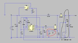
I am building own boost converter using UC3843

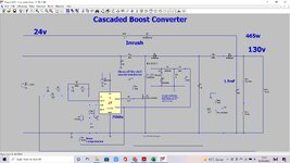
- the input voltage = 24v
- the input current = 3A
- i want adjustable voltage from 150v to 235v using potentimeter
- the current output = 0.3A
- Peak inductor current = 4.5A
- min. duty cycle = 84% - Max. = 89.7%

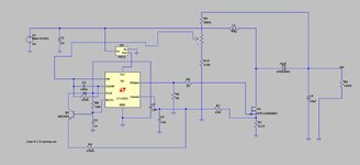
this is my schematic in thattachment

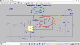
since this circuit will be powered mainly in DCM mode and its cycle duty higher than 50% so i want to add slope comp.
how to calculate the resistor and capacitor of slope comp. (marked in red)?

the second question how to adjust the output voltage range between 150 to 235v using potentimeter
the feedback pin has voltage divider of two 10k ohm resistor to give 2.5v, but i want to know how to calculate the value of potentimeter i need to add here to adjust the output voltage range between 150 to 235v?
 

Attachments

  • 244.JPG
    244.JPG
    68 KB · Views: 193
Rs/Cs have nothing to do with slopecoompensation. Refer to UC3832 datasheet for slope compensation circuit.
Slope compensation is however required in CCM, not DCM.
 
if there are not so why they are there in in the datasheet and where is the slope comp?

do you think this circuit need slope comp.? it is DCM but may be enter CCM at max load for example
 
Rs/Cs is filter for current sense, as suggested in datasheet.

Here's the slope compensation circuit, adding a transistor and resistor to the basic design

1000002641.jpg
 
A single boost converter has to struggle to give you 150V 0.3 A (according to my simulation).

The longer the duty cycle, the shorter portion of cycle for jolting the output.

Expect to raise the Amperes going into the system in one way or another. Interleaving two boost converters is a method and is feasible with a second identical coil.

clk-driv boost conv NPN 24V 120kHz 170V 300mA.png
 
Hi,

Potentiometer:

I didn`t read the datasheet. You say feedback voltage is 2.5V and you want the output voltage to be adjustable from 150V to 235V.

first: 10k/10k makes no sense.
so how to calculate the voltage divider:
You have this situation: (from bottom to top)
GND -> lowerLegResistor Rl-> [FB = 2.5V] --> upperLegResistor Ru--> OutputVoltage

Voltage behaves like resistors, this means the higher the voltage the higher the resistor.

so for 150V:
V_RL = 2.5V, V_Ru = 150V-2.5V = 147.5V
Ru = (147.5 / 2.5) * Rl = 59 * Rl

for 235V:
V_RL = 2.5V, V_Ru = 235V-2.5V = 232.5V
Ru = (232.5 / 2.5) * Rl = 93 * Rl

According your schematic Ru is constant, Rl is variable.
so let´s say Ru = 1M
then for 150V: Rl = 1M/59 = 16.95k
for 235V: Rl = 1M/93 = 10.75k

the pot is the "variable value" (from 10.75k to 16.95k) = 6.20k

now you probably will not find a 6.2k pot, so you may rather choose an 10k pot.

if using a 10k pot: the factor is 10k/6.2k = 1.613
Use this factor to multiply with alll other resistor values.

Klaus
 
a single stage boost ckt will struggle to go from 24V to 235V, the required duty cycle is just over 90% to account for losses.

At this duty cycle you will struggle to stay in DCM unless the L is quite small

so yes, CCM with slope comp.
 
also, attached please find a cascaded boost, which may be very good for you. In LTspice and jpeg.

There really are no problems with cascading, people always think that the both stages need source current limiting, but they dont....just one of them, the one "upstream".

Also a report on slope comp
 

Attachments

  • cascaded boost_24 TO 130.zip
    2.1 KB · Views: 40
  • cascaded boost 24v to 130v.jpg
    cascaded boost 24v to 130v.jpg
    240 KB · Views: 121
  • _5 Current Mode Control Modeling.zip
    1,012.6 KB · Views: 42
Last edited:
Hi cupoftea
Thanks for sharing this circuit but i can not understand why you used this transformer circuit( marked in brown)
And what is this resistor and diode for?(marked in green)
And how you calculated these two inductors? ( marked in yellow)
I want at least output max 230v 0.2A

I have made this circuit 24v to 240v 0.21A and i stimulated it and i think it's working probably, after all these replies i have some worries about it as wont work probably as it is single boost converter but i see many boost converters in the market have higher ratio of my circuit ratio

For example yh11068a its input 12-24 and out put 400v at 0.2
 

Attachments

  • cascaded boost 24v to 130v.jpg
    cascaded boost 24v to 130v.jpg
    253.1 KB · Views: 49
  • Boost 24 to 240.zip
    1.4 KB · Views: 43
  • 2 (1).JPG
    2 (1).JPG
    75 KB · Views: 89
it says it is a current transformer - to see the current in the 1st mosfet - used by the IC for control purposes.

Just be aware that your simulated ckt may not work as well as you hope in the real implementation.
 
Thanks, the in green bit is so that inrush doesnt go through the main inductor and cause overvoltage ringing.
--- Updated ---

attached i have givien you 24v to 235v at 90w. (LTspice sim)
This will work pretty much as the sim, as long as you lay out properly.

There is no right or wrong inductor value....but i gave you BCM operation at the downstream bit, so you reduce reverse recovery losses there.......woops, sorry, i made it 90w instead of 60w...but you can easy change for that
--- Updated ---

to get varying vout, use external error amplifier, and vary the reference voltage into it.

The superb magic of the cascaded boost is that the downstream mosfet, never sees any overcurrent....even though its own current is not limited directly.
 

Attachments

  • cascaded boost_24 TO 235 90w.zip
    2.1 KB · Views: 34
Last edited:
By interleaving two boost converters you gain some advantages. Example, smoother current draw from supply, and reduced stress on components.
Frequency slower than 40-50 kHz allows you to get by with ordinary diodes.

twin interleaved boost conv 24V to 250V clk-driv 40kHz load  250mA.png
 

LaTeX Commands Quick-Menu:

Part and Inventory Search

Welcome to EDABoard.com

Sponsor

Back
Top