cupoftea
Advanced Member level 5
Hi,
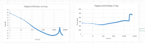
I have done an LTspice Flyback simulation just inside CCM with 0.55 Duty.
Added a bit of slope compensation, which didnt make the sim unstable, though
the bode plot shows the gain coming back up to the zero dB line as attached.
Would you say this , on the bench, would not be likely to cause sub-harmonic oscillation?
The bode plot is using Bassos 2A-24 equation on p233 of his book "switch mode power supplies"
Error Amp tran func uses Bassos Type 3 TL431/Opto from his book "designing control loops...."
Flyback Vin = 90v, vout = 24v, Ns/Np = 19/84, Ls = 54.2uH. Fsw = 66kHz, Load = 1A
Reducing the slope compensation actually reduces the high freq peak back below the 0dB line.