Continue to Site

Welcome to EDAboard.com

Welcome to our site! EDAboard.com is an international Electronics Discussion Forum focused on EDA software, circuits, schematics, books, theory, papers, asic, pld, 8051, DSP, Network, RF, Analog Design, PCB, Service Manuals... and a whole lot more! To participate you need to register. Registration is free. Click here to register now.

TS 555 CN 50 duty cycle problem

Status
Not open for further replies.

boylesg

Advanced Member level 4
Joined
Jul 15, 2012
Messages
1,023
Helped
5
Reputation
10
Reaction score
6
Trophy points
1,318
Location
Epping, Victoria, Australia
Activity points
11,697
Can any body tell me what I have done wrong with this circuit - I just cant see it.

I am trying to implement this circuit.

1666966873965.png


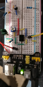
Here it is on my bread board. The transistor circuit is not connected atm. R1 = 100k as per above schematic. R2 is a 10k trimpot. C1 = 10nF
But I am getting a steady 5V out of pin 3 - no oscillation whatever.
1666966947701.png
 
Last edited by a moderator:

Hi,

what does the red wire on pin5 do? It´s not according the schematic.

Klaus
 

More than once I've hooked together a 555 pulse generator (hardware) and I saw constant supply voltage on the oscilloscope. When in truth it was about 99 percent duty cycle! Low state lasted so briefly it didn't appear onscreen at first until I adjusted a few dials.

By applying various volt levels to pin 5 (Ctl pin), I change duty cycle. The 555 is constructed to do that. Yet most designs just put a capacitor to ground.
 

Status
Not open for further replies.

Part and Inventory Search

Welcome to EDABoard.com

Sponsor

Back
Top