Continue to Site

Welcome to EDAboard.com

Welcome to our site! EDAboard.com is an international Electronics Discussion Forum focused on EDA software, circuits, schematics, books, theory, papers, asic, pld, 8051, DSP, Network, RF, Analog Design, PCB, Service Manuals... and a whole lot more! To participate you need to register. Registration is free. Click here to register now.

transformer oscillation/timer drive circuit

Status
Not open for further replies.

Darki

Newbie level 6
Joined
Mar 24, 2007
Messages
12
Helped
0
Reputation
0
Reaction score
0
Trophy points
1,281
Activity points
1,373
I have a proplem.
I need at circuit there can drive my transformer. I have a oscillation/timer circuit wich look like this:
**broken link removed**

But i cant get it to work. Anybody have any idea what could be wrong?

Sorry for my bad english hope you understand me anyway :)[/img]
 

Hi,

The PHASE SHIFT via a single RC stage is not enough, a single RC stage shifts 60 degree only...

Consider this circuit and try to connect its output to the input of your stage (disconnect C1 from Q2 emitter: this leg will be connected to the output of the one transistor RC phase shift oscillator in this link):

**broken link removed**

Notice: this link and some others may be also of some help for your sparks..

http://www.angelfire.com/electronic/cwillis/fetcoil.html

(Copy and paste the above links into your web browser without ** in the http and replace them with tt of course)

unkarc
 

hmm it looks very confusing that circuit and i dont realy understand howe i should use it.
Do you have a simpler circuit, or can you explain it better?

The only thing i need it to do is to turn the power on and off on the transformer.
 

Darki said:
The only thing i need it to do is to turn the power on and off on the transformer.

Hi,

Question is at what frequency you need to turn it on and off?

In the simplest case you could use a slightly modified circuit of yours I attached
[/img]

The value of R1 and C1 needs experimenting. R1=1 to 10 MegaOhm C1=100-470-1000-2200uF electrolytic capacitor.
It is supposed to work like this: when you switch on power C1 is empty and starts charging up through R1. When the voltage is as high as 2 x Vbe = 1,4V the two transistors switch on, you get a spark. At the same time the base current slightly discharging C1 below 1.4V and the charging process starts again. It is possible that the base current is so small (due to the Darlington transistors) that C1 is unable to discharge: then you can try to omit Q1 and use only Q2, this definitely increases base current need, hence C1 is able to discharge more readily. Or increase R1 further up to reduce charge current so that the discharge current via the base of Q1 (or Q2) can be stronger than the charge current, this is the trick to make your circuit oscillate.
Diode in parallel with the coil is a back EMF killer, it protects Q2 from any induced overvoltage, it can be 1N4007 type, use 2 or 3 in parallel to increase its 1A forward current rating if needed.
regards, unkarc
 

That sound like i will work :O

I will try that :D

Added after 4 hours 13 minutes:

Now i have experimented with a 1 M ohm pot resistor, a 330mF 200v capacitor and a 220mF 25v capacitor. But i still cant get it to work.

I can see the capacitor slowly charging if i mesure over it, and i can see the volt on the emitter of the transistor raisingt. But the capacitor wont discharge again.

I have tryed with both transistor Q1 and Q2 and with Q2 alone but it give the same result.

Maybe i use a wrong transistor or somthing, or maybe i just have to experiment with another R1 and C2 value?

I got my transistors from a old tv/monitor.
They are called:
IRFC50 and BU 2527AP
 

Hi,

I know BU2527AF but never heard IRFC50, maybe this latter is a Power MOSFET? and not a bipolar transistor like the BU? You have a data sheet on it? I cannot find any data on it, probably became obsolote?

Here is data sheet on the BU2527AF:
https://www.datasheets.org.uk/search.php?q=BU2527&sType=part&ExactDS=Starts

Check the pins of the BU2527 as follows: I assume you have a multimeter that has a diode checker position? if yes, place the transistor on the table with the three pins facing you, and you must see type number side on its top. Now the pins are base, collector and emitter, from left to right. Place multimeter positive probe to the base and touch first the emitter with the negative probe: you must see something like between 700-800mV. Now put the negative probe from the emitter to the collector, positive probe stays at the base: you must see very similar in that range too. Now place positive probe to collector and negative probe to the emitter: you must see an open circuit as if you had measured no transistor.

If you cannot find similar behavior with your BU as I tried to describe, your transistor is faulty.

Re IRFC50 if this is a bipolar transistor, you probably can check it in the same way as the BU but if it is a MOSFET (I guess it is) it needs a different testing: also in Diode Test position your multimeter, put positive probe to the Gate and the negative probe to the Source. Now lift up the pos probe tip from the Gate (the negative probe tip stays at the Source) and put the positive probe tip to the Drain: you must see near zero (000.00) on the display. Now put a short circuit onto the Gate and Source pins for a few seconds after removing the probe tips (you discharge the inter electrode capacitor with a piece of wire because you have charged it up with the voltage from the multimeter probes) and now check again between the Drain and Source with the multimeter Diode test or low Resistance test, you must see an open circuit, not an almost zero like before!

It is possible you all know this and you are sure your transistors are ok?
Then it is also possible my suggested modification cannot work.... will think on it tomorrow

unkarc
 

I have not teste them like that but i will try later today.
I tink they work..

No i dont have a datasheet on IRFC50.. But i will test it the way you tell me and see what it is :)
 

Hi Darki,

I am sorry but my circuit modification is not good, it cannot oscillate!

So you have to use either the 1 transistor RC oscillator I gave a link earlier or a well known timer IC like 555. I drew a circuit on this, see the attachment.
You cannot go higher than +15V for the LMC555CN timer IC, I recommend using a 9V dry battery because the IC is a CMOS version and needs very little current, the battery will not discharge for long months and by the way this timer IC is able to work with even as low as 3V supply!

The negative battery pole of this timer circuit (with the ground symbol) has to be connected to the negative pole of your power supply, I put a ground symbol on your circuit negative pole too. The other connection from the timer circuit to your circuit is through a 10uF capacitor, that is all. This capacitor couples the square wave pulses from the timer output to the base of your transistor. I think you can omit Q1 completely and use only your Q2, the 10-100kOhm (exact value not critical in this range) resistor goes to the base of Q2 instead.
The ability to vary the pulse frequency and its duty cycle is good possibility for creating various sparks if you are interested in this.

Regards
unkarc

PS: Here is a link to the timer IC data sheet:
**broken link removed**

And this the Electronic Design Magazine article I used its Fig.4 to combine with your switching circuit:
**broken link removed**
 

Ohh yes i just found this other cuiciut:
http://www.geocities.com/CapeCanaveral/Lab/5322/fbt2.htm

Wich uses the 555 IC too.

I will try one of them. When i get my my fingers in a 555 IC, maybe first in a week :cry:

Is there any big difrent on the difrent types of IC 555? I noticed there are several difrent numbers of them[/url]
 

Hi,

Yes the circuit your link shows is also good, it uses a Power MOSFET for switching and it needs that transistor 2N2222 to drive the Gate correctly and safely.

Re the different types of 555: in fact the original circuit was made in bipolar IC manufacturing process and type # is NE555 and several big semiconductor firms produced it under their own names, the 555 number was included.
The CMOS manufacturing process has the advantage of much less current consumption need from the power supply and still with the same or even better characteristics with respect to the bipolar version.

The letter designations after the 555 mean case and temperature variations, the cheapest is the 8 pin dual-in-line plastic case the LMC555CN from National Semiconductors or look for Texas TLC555CP at www.ti.com for data sheet, I think Thomson also makes it.

Any variant in the dual-in-line case is pin compatible with each other and with the original NE555 pin out.

If you have problems in getting the CMOS version,, then you can use any of the NE555 or LM555 bipolar types too, the only 'drawback' is the 9-10mA current consumption of these bipolar versions versus the 0.5mA CMOS one.

unkarc
 

If you are using an ignition IGBT, you can drive that IGBT directly from the 555 without any other transistor in between. The Motorola MGP20N40CL is a nice IGBT for ignition coil drive. It has internal clamping diodes for voltage protection (400V) and can handle 20 amps. In practice, with peak coil currents of 10A, it only needs a small heat sink.

Harris has also really nice Ignition IGBT's that work extremely well. But you need a heatsink on that IGBT at higher currents.
 

Interesting ideas you come up with Thx for that :D

But now i have found 2 great working transistor and made this circuit:
**broken link removed**

And it works good and can handel more than 15 volt :)
Now i just need a way to get it to drive my transformer.

I tyred to connect my transformer between the emitter and minus on one of the transistors and i actually got around 10 volt out of it (not very effektive).

Now i need another way to connect it whic can lead more current into my transformer.

Maybe some kind of amplifiere circuit i connect to the output of this circuit like the one in the link i poste before, maybe that will work?
 

Hi,

Yes it can be connected to your original circuit shown, I attached the connection as it can be done.

Good luck!

unkarc
 

unkarc said:
Hi,

Yes it can be connected to your original circuit shown, I attached the connection as it can be done.

Good luck!

unkarc

Uhh yes that look like somting. I will try that tomorow :D
 

It worked kind of... But the BU2527AF died when i connected it to a 12 volt 4.5 amp battery... And it was rated 15amp? Strange :cry:

The Motorola MGP20N40CL's datasheets say it can take 20 amps is that right?
Datasheet: http://www.datasheetcatalog.net/pt/datasheets_pdf/M/G/P/2/MGP20N40CL.shtml

What is the normal price for it or what divice can i find it in?

Do i need to change anything on the circuit to trigger the Motorola MGP20N40CL ?
 

There are several good Ignition IGBT's that you can use.

Here is another one:
FAIRCHILD
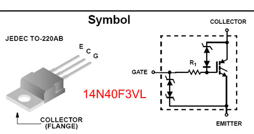
14N40F3VL
Code:
http://www.dzjsw.com/cxyg/h/HGT1S14N40F3VLS.pdf

This IGBT has also built in Voltage Clamp between drain and gate and ESD protection.
There is nothing easier than this to have any coil or inductive load run.

You can get them from many places on the net for around $ 2 to $ 3 depending on quantity.
86_1175864376.jpg
 

Ohh

What is the advantage on using a MOSFET or the IGBT instead of a normal transistor?
 

Darki said:
It worked kind of... But the BU2527AF died when i connected it to a 12 volt 4.5 amp battery... And it was rated 15amp? Strange :cry:

Hi,

(the BU2527AF is rated at 12A continuos or 30A peak current, ok? from data sheet)

I assume your 12V 4.5Amp battery means for you 4.5 AmperHour, right? It means that you can load your 12V battery with 1 Amper for 4.5 hours or load with 4.5A for 1 hour and so on with the current-hour combinations to remain at or under 4.5AH, right?
SO the BU2527AF could be died for two reasons: either DC over current or inductive overvoltage. I suspect Over current through its collector-emmiter because when the transistor opens/switches on, its ON resistance is well under 1 Ohm and from your 12V battery the current through the switched-on transistor can be very easily higher than 12Amper (the continuous collector current limit). Because there is no any other resistance in your circuit which could limit the current not going higher than 12A. So the solution is to include a high wattage resistor of at least 1.2 Ohms in series with your positive battery wire which will let only flow about 10 Amper max towards the collector-emitter path, ok? (considering a full switch-on for your BU transistor, the 10 Amper max current limit will be within its 12 Amper capability)

Another possibility would be to reduce the duty cycle of your switching signal to reduce current through the switch (the less time you keep the switch ON the less current is able to flow that would distroy the switch) but in case of your present astable 2 transistor multivibrator it is not easy to reduce, in case of the 555 timer circuit I showed it is much easier with one of the variable resistors.


Do i need to change anything on the circuit to trigger the Motorola MGP20N40CL ?

Basically NO, but to be a 100% sure an oscilloscope would be needed to see the waveform on the collector of one the your astable multivibrator transistors and check if the transistor switches fully on or not: in case it switches fully on it means that the DC voltage on its collector goes down to as low as 0.2 to max 0.5V with respect to its emitter (which is the negative ground) because this low voltage would insure the full switch off of your IGBT (or MOSFET) device. (Because they switch on usually at a positive gate source threshold voltage of a few Volts, in case of MGP20N40CL this threshold is a minimum of 0.75 to 1V from data sheet.) And if your astable multivibrator transistor does not go under 0.75V at its switch-on time then it cannot correctly switch OFF the IGBT (though capacitive coupling instead of the present direct coupling from its collector to the gate of the IGBT may help on this situation a little). What I included in the schematics is two resistors, a voltage divider to help reach the situation of bringing the off voltage below 1 Volt for the switch. Some tinkering with the resistor values may be neccessary as I included in the schematics.

A notice: if you use the IGBT transistor rated for 20 Amper, it may still suffer from overcurrent, because the inner resistance of your battery usually is around or under 0.1 Ohm and AGAIN there is NO any current limiter in your circuit to protect the IGBT!
(Remember if you make a short circuit on you battery how much current is able to flow into the wires?)

unkarc
 

ohh I did not know that about the battery. Yes the battery says 4.5Ah..
Maybe i should use a resistor.

I have thinked about using a oscilloscope. I have actually tied with my computer's sound card and i got a signal like this:
**broken link removed**
It look like it goes down to 0 volt but im not sure i have calibrated the oscilloscope program right.

I will try to test it again on a real oscilloscope later this week.

I just tested the battery with i think a 40 amp car battry carger meter (or somthing like that). The nedel showed more than 40amps and the wires are getting extremly hot. Very efektive battery :D
 

Hi, I need a transistor equivalent data sheet. Can anyone help me?
Mithun.
 

Status
Not open for further replies.

Similar threads

Part and Inventory Search

Welcome to EDABoard.com

Sponsor

Back
Top