neazoi
Advanced Member level 6
Hello,
I am trying to build a simple form of single bit ROM (core rope memory) for illustration purposes.Before proceeding with the design, I am making some tests on a transformer.
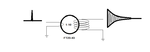
The picture shows a pulse comming out of a 555 timer, into one turn on the primary.
The secondary is connected to an oscilloscope.
Every time a pulse occurs on the primary, I get this strange waveform on the secondary. It is a sine wave and it's amplitude degrades over time.
I need a brief explanation of why is this happening?
Also is there any way to practically find at what point a square curve core is saturated?
I am trying to build a simple form of single bit ROM (core rope memory) for illustration purposes.Before proceeding with the design, I am making some tests on a transformer.
The picture shows a pulse comming out of a 555 timer, into one turn on the primary.
The secondary is connected to an oscilloscope.
Every time a pulse occurs on the primary, I get this strange waveform on the secondary. It is a sine wave and it's amplitude degrades over time.
I need a brief explanation of why is this happening?
Also is there any way to practically find at what point a square curve core is saturated?