jayc73
Newbie level 5
Hi all,
Jay is my name and Western Australia is where I am.
I have some basic understanding of electronics , enough to keep me out of trouble anyway.
I've decided to try and make a simple device but very unsure of how to go about it.
In a nut shell, I wish to use a dual axis tilt switch to perform a couple of functions.
Hopefully this drawing will help.
Both input and output sides are divided in two ( operating 2 different components)
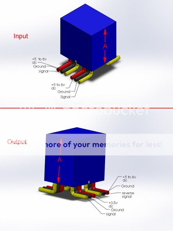
Basically, I'm looking for a dual axis tilt switch that will activate at 45 degrees on either axis .
When the tilt switch is not activated, the input side is passed directly to the out put side - no change .
When the tilt switch is activated , one half of the output side drops voltage to 3.5v ( 3v to 3.7v would be the minimum and maximum drop) and the other half over rides the signal and reverses it.
I did forget to mention, input voltage will be between 5 and 8V DC
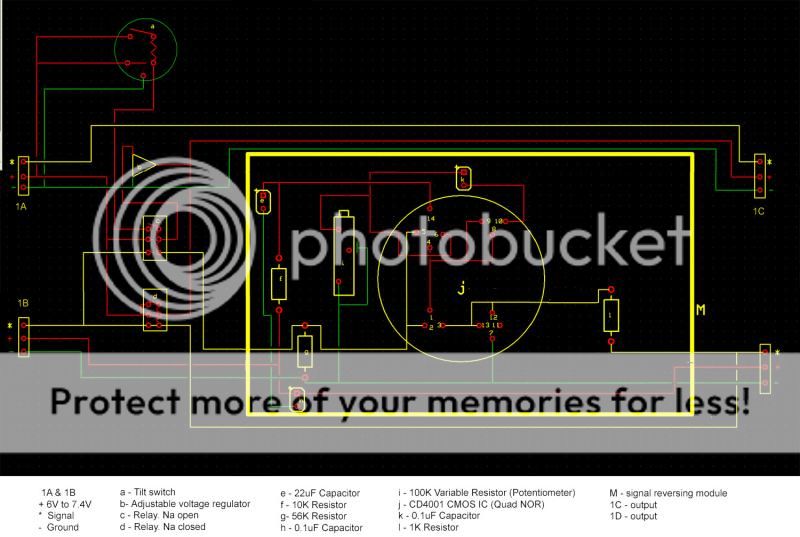
I found this schematic which I can follow without too many problems for reversing the signal but I'm tot too sure on how to integrate this with a tilt switch.

Parts
(1) CD4001 CMOS IC (Quad NOR)
(2) 1K Resistor
(1) 10K Resistor
(1) 56K Resistor
(1) 100K Variable Resistor (Potentiometer)
(2) .1uF Capacitor
(1) 22uF Capacitor
When it comes to the voltage drop, can I use resistors to do this ? and again, how would I integrate this ?
Hopefully I've made it easy to understand and any help would be fantastic.
Jay is my name and Western Australia is where I am.
I have some basic understanding of electronics , enough to keep me out of trouble anyway.
I've decided to try and make a simple device but very unsure of how to go about it.
In a nut shell, I wish to use a dual axis tilt switch to perform a couple of functions.
Hopefully this drawing will help.
Both input and output sides are divided in two ( operating 2 different components)
Basically, I'm looking for a dual axis tilt switch that will activate at 45 degrees on either axis .
When the tilt switch is not activated, the input side is passed directly to the out put side - no change .
When the tilt switch is activated , one half of the output side drops voltage to 3.5v ( 3v to 3.7v would be the minimum and maximum drop) and the other half over rides the signal and reverses it.
I did forget to mention, input voltage will be between 5 and 8V DC
I found this schematic which I can follow without too many problems for reversing the signal but I'm tot too sure on how to integrate this with a tilt switch.
Parts
(1) CD4001 CMOS IC (Quad NOR)
(2) 1K Resistor
(1) 10K Resistor
(1) 56K Resistor
(1) 100K Variable Resistor (Potentiometer)
(2) .1uF Capacitor
(1) 22uF Capacitor
When it comes to the voltage drop, can I use resistors to do this ? and again, how would I integrate this ?
Hopefully I've made it easy to understand and any help would be fantastic.