idoit
Newbie
Hello everyone,
I was working on my ThinkPad X230 Tablet and accidentally cut one of the very thin wires (0.2mm thickness). It turns out it was the ground wire (GND) for digitizer. There are 5 thin wires for digitizer and here is the schematic for it:
pin description
23 USBP4+
24 USBP4-
25 STOP
26 VCC3BLEDBD
27 GND
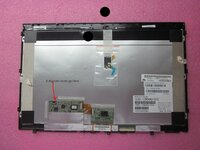
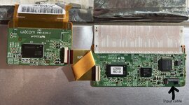
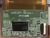
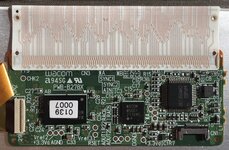
I turned the laptop with wires 23-26 all active and flowing to digitizer board BUT ground wire not connected (cut). Now when I turn the laptop on, neither touch nor pen is working. I tried and soldered wire 27 back together and turned the laptop on. Same, no finger touch or pen. They are not recognized under Windows either. I have attached high quality photos of both finger touch and pen/stylus PCBs.
I was wondering what happened? Have I fried the digitizer pcb? Anyway to identify which component got damaged and fix it? Any pointers are welcome. Thank you!
I was working on my ThinkPad X230 Tablet and accidentally cut one of the very thin wires (0.2mm thickness). It turns out it was the ground wire (GND) for digitizer. There are 5 thin wires for digitizer and here is the schematic for it:
pin description
23 USBP4+
24 USBP4-
25 STOP
26 VCC3BLEDBD
27 GND
I turned the laptop with wires 23-26 all active and flowing to digitizer board BUT ground wire not connected (cut). Now when I turn the laptop on, neither touch nor pen is working. I tried and soldered wire 27 back together and turned the laptop on. Same, no finger touch or pen. They are not recognized under Windows either. I have attached high quality photos of both finger touch and pen/stylus PCBs.
I was wondering what happened? Have I fried the digitizer pcb? Anyway to identify which component got damaged and fix it? Any pointers are welcome. Thank you!