Continue to Site

Welcome to EDAboard.com

Welcome to our site! EDAboard.com is an international Electronics Discussion Forum focused on EDA software, circuits, schematics, books, theory, papers, asic, pld, 8051, DSP, Network, RF, Analog Design, PCB, Service Manuals... and a whole lot more! To participate you need to register. Registration is free. Click here to register now.

Dehumifiier LAF VEAB not working

PaulsM

Newbie level 5
Joined
Dec 3, 2023
Messages
8
Helped
0
Reputation
0
Reaction score
2
Trophy points
3
Activity points
74
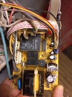
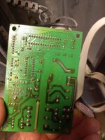
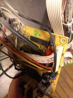
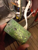
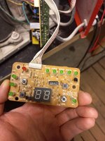
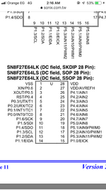
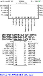
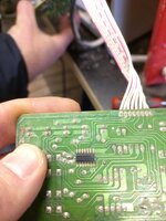
Hello. Maybe someone here could help me troubleshooting. This is a control of a dehumidifier. So, if machine is plugged in 230V, speaker on board makes a beep and It wont turn on, nothing works. I tested power regulator (third picture), its 7805C, input 18V, output 5V, fourth picture is datasheet for that regulator. Fifth picture is transformer, couldnt find datasheet for that, but it clearly says 12V, is that a problem? I guess not. What could I look for next? Fuse is OK. Curious to solve problem myself and learn something, thank you for your time in advance.

1f642.png

406209630-10222894612056655-2085596323779515780-n.sized.jpg
WhatsApp-att-ls-2023-11-28-plkst-21-01-45-9cc28e50.sized.jpg
WhatsApp-att-ls-2023-11-28-plkst-21-02-20-4d2d85b7.sized.jpg
406261663-10222894614576718-544724079463287960-n.sized.jpg
406227841-10222894612656670-2321742511324315131-n.sized.jpg
 
If you are measuring 5V out of the 7805 the transformer and regulator are working properly. The problem is more likely to be the controller board or one of the sensors. The pictures don't show any MCU but there must be one to make the display work, can you send a picture of the underside of the controller board please.
Do any of the LEDs light up? If so, which ones, tell us their purpose rather than their location on the board.

Brian.
 
Transformer 12VAC produces 18V peak. The 7805 regulates it down to 5VDC. I guess one beep means the board has minimal power at least for a few seconds.

However since nothing else works then perhaps power has become inadequate to operate other components. Example, it appears there are 1 or 3 relays on the board. Maybe they activate from 5V, but if no component is working then maybe the relays are supposed to click but do not since they lack power?

Is another voltage regulator present such as 7809 (9 volt)? 7812 (12 volt)?
Do you measure correct readings from it?
 
Hi,

maybe it is supposed to be switched OFF, because
* too low humidity in the air already
* watertank full
* timer operation
* overtemperature

Maybe there is
* a malfunction of these sensors (temp, humidity, water level...)

Klaus
 
Compressor power relays has 12V coil, probably also the two smaller relays. So we apparently have unregulated 12 V and regulated 5 V, as in many appliances.
You should check that 5V rail has no superimposed AC, e.g. due to dryed out filter capacitor. If so, it might keep processor in reset. I guess, 50 % of non-operational appliances have a similar fault.

What is the expected display state? Only lighting up on key-press or permanently displaying some info?
 
Hi,

so when powered there is no display, no LED, no sound (except the short beep) ... nothing?
What happens on button press? nothing?

Klaus
 
Hello again. Thank you for your input :)
So, when I plug it in, it beeps once. I think it did that previously too. No LED light or numbers on panel work. None of buttons do anything. As I can remember, display should go on when ON button is pressed. Some more pictures here. I tested power regulator with multimeter.
Here are some more pictures with both boards. On tested ON button itself, it works. There are 4 buttons - ON/OFF - HUM (humidity level) - Speed (fan speed) - and timer.
 

Attachments

  • WhatsApp attēls 2023-12-03 plkst. 17.52.10_d1b6f94f.jpg
    WhatsApp attēls 2023-12-03 plkst. 17.52.10_d1b6f94f.jpg
    332.5 KB · Views: 73
  • WhatsApp attēls 2023-12-03 plkst. 17.52.10_3db5e95c.jpg
    WhatsApp attēls 2023-12-03 plkst. 17.52.10_3db5e95c.jpg
    274 KB · Views: 61
  • WhatsApp attēls 2023-12-03 plkst. 17.52.11_b38c2a17.jpg
    WhatsApp attēls 2023-12-03 plkst. 17.52.11_b38c2a17.jpg
    240.4 KB · Views: 59
  • WhatsApp attēls 2023-12-03 plkst. 17.52.14_4cec4433.jpg
    WhatsApp attēls 2023-12-03 plkst. 17.52.14_4cec4433.jpg
    226.4 KB · Views: 57
  • WhatsApp attēls 2023-12-03 plkst. 17.52.14_aaef386b.jpg
    WhatsApp attēls 2023-12-03 plkst. 17.52.14_aaef386b.jpg
    247.6 KB · Views: 70
Before going any further, there is a lot of corrosion on the display board, given it is in a high moisture environment that might be expected.
Use the Ohms range on your multimeter to check for continuity along the tracks. I'm suspicious that they may have corroded through and connections may no longer be being made. Find a solder joint at one end of a track and check the resistance to all the other joints on the same track. If any measure more than about 1 Ohm your fault is found. Do not measure between tracks as that could damage the microcontroller. If a track is open circuit, given the general condition of the board I would not attempt to bridge the break, instead solder a wire, as short as possible, between the nearest solder joints to each side of the break.

If the tracks are OK and it still doesn't work, power it up and measure the voltage between pin 1 and 32 of the processor (the SONIX IC), these are the corner pins with the 'half moon' between them in the package molding. I can't see it in the picture but I'm guessing its the end nearest CN4. Tell us what the voltage measures.

Brian.
 
The transformer look so much black, I mean it’s coil wires look bad, are you sure that transformer is ok?
--- Updated ---

Does the 5v goes to the panel?
 
Hello. Thanks for your time and input :)
Its cold in my garage, so I spend a little time for this. This is how far I got. Small board receives 5V, that goes to small chip and 5V is on empty pin. Button is connected to controller`s (SN8F27E64KB) one pin. 2 button pins (of 4) have 0 ohms to controller.
WhatsApp attēls 2023-12-04 plkst. 20.34.01_94b8f458.jpg
WhatsApp attēls 2023-12-04 plkst. 20.34.02_2ac3f2df.jpg
 
Pin 1, the one you arrowed in the second photograph is the VSS pin (aka 'ground') so it is normal for the switch to connect there, you might find the other switches also have one side connected there.

The board should function as long as the 5V from the power supply is there and I think we have established it's OK. From the photographs, what concerns me is the state of the copper tracks, especially the ones around the edge of the board. The whole underside, except for the solder joints should be a uniform green color, its a kind of pain layer to prevent moisture reaching the copper tracks. If you look at most of the tracks they seem to have a mottled color and that indicates the copper has corroded. If corrosion has completely eaten through a track, it will no longer provide connection along it, we call it going 'open circuit'. With the power turned off, use the Ohms range on your multimeter (if it has a range switch, use the lowest range) probe along each track, following the line of the copper but only putting the probes on the solder joints. I'm trying to establish whether any of the tracks are failing to connect the solder joints together. Try not to probe between different tracks because the meter applies a voltage to do its test and you should try to avoid it being placed across sensitive parts. Along copper that should be linking places anyway should be safe.

If you want to try cleaning the track side of the board to make the tracks more obvious, use isopropanol (isopropyl alcohol) and scrub it gently with an old toothbrush, letting any excess liquid drip off, then when clean, mop it dry with a tissue. Don't switch on until all the remaining alcohol has evaporated.

Brian.
 
Also you may check the input voltage of the mcu, I’ve looked at the data sheet and attached the pin configuration gor you to find the vdd pin

Check the voltage and let’s know
 

Attachments

  • 360D1975-F590-4316-B70E-AC898BE96608.png
    360D1975-F590-4316-B70E-AC898BE96608.png
    178.5 KB · Views: 44
  • EA6E5E89-6044-4A0B-B668-4F2137669CB9.png
    EA6E5E89-6044-4A0B-B668-4F2137669CB9.png
    188.5 KB · Views: 46
Ok, will try, thank you. VSS is ground, which one is +5V? VDDL (pin 28) or VDD/AVREFH(pin 27)?
 
Probably both. VDD is the 5V supply on pin 28, the VDD/AVREF on pin 27 is the reference voltage to the IC's internal analog to digital converter (ADC). It can be less than VDD but not more. For more accurate analog measurements it is sometimes better to use a lower voltage or a better filtered 5V as any noise on the reference will make the voltage measurement less consistent. In a dehumidifier where accuracy isn't very important they are probably both 5V if the ADC is used at all.

Brian.
 
It does have supply. The Sonix IC is the microcontroller that does all the 'thinking' about how the unit works. it reads the sensors, does the calculations and drives the LEDs and relays to switch the motors. The 5V between VSS and VDD pins is the supply it needs to run. There are other possible electrical problems but it is essential to confirm all the tracks and connections are working first. Most people target the biggest or most complicated components first when the real problem is often the smallest parts or a mechanical fault. My guess is you have a connection failure, possibly along one of the tracks, that is 'confusing' it and stopping it's normal start up routine.

Brian.
 
Didnt have much time on this today. So, controller "gets" around 2.6V supply, datasheet says its needs 1.8V to run. I guess that when its plugged in 230V, it beeps, it means controller is supplied. There is a small IC on control board and it has no code on it, I guess it communicates with main board controller. ON button works and has no resistance in between main controller. I will check all small board connections as soon as I can :)
 

Attachments

  • WhatsApp attēls 2023-12-05 plkst. 21.19.42_75892a05.jpg
    WhatsApp attēls 2023-12-05 plkst. 21.19.42_75892a05.jpg
    268 KB · Views: 44

LaTeX Commands Quick-Menu:

Part and Inventory Search

Welcome to EDABoard.com

Sponsor

Back
Top