- Joined
- Apr 1, 2011
- Messages
- 15,205
- Helped
- 2,901
- Reputation
- 5,814
- Reaction score
- 2,985
- Trophy points
- 1,393
- Location
- Minneapolis, Minnesota, USA
- Activity points
- 113,942
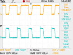
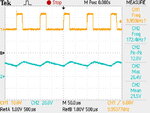
The waveform looks better without the capacitor.
I have been trying in various ways to get a waveform like you get with the capacitor. It looks like ringing due to LC oscillations. However the cap also appears to produce a volt level which interferes with operation. It's as though the active component(s) lose their reference. This might occur (for example) when the bias can't turn on a transistor/mosfet due to the emitter leg being at too high a volt level.
One thing I often see in simulations, is high-frequency ringing after the coil has discharged. These go away as soon as the transistor turns on. I have found it helps to install a 1k resistor across the diode. Try lower values as necessary.
---------- Post added at 12:54 ---------- Previous post was at 12:22 ----------
Also remember, a charged coil must never be isolated by sudden high resistance, even momentarily. The current must have somewhere to go.
Otherwise the collapsing flux field will generate a high voltage kick which will go through neighboring components, quite possibly ruining them.

