Continue to Site

Welcome to EDAboard.com

Welcome to our site! EDAboard.com is an international Electronics Discussion Forum focused on EDA software, circuits, schematics, books, theory, papers, asic, pld, 8051, DSP, Network, RF, Analog Design, PCB, Service Manuals... and a whole lot more! To participate you need to register. Registration is free. Click here to register now.

sync buck convrter problem

Status
Not open for further replies.

haywire

Newbie level 6
Joined
May 16, 2010
Messages
13
Helped
0
Reputation
0
Reaction score
0
Trophy points
1,281
Location
malaysia
Activity points
1,398
hi everyone..
i did post a lot here regarding the same project. sync buck converter for LED driver. initially, the circuit provided very good results.
but after a long time of testing and trying to change this ad that every now and then, the buck converter now won't work. both the IGBT's signal seems to be overlapping and the IGBT heats up causing the circuit to fail.
i wonder why is this happening..

so, i'm left with 2 choices.
1. to go for the conventional buck converter. i did try this one, but the results seems weird because the diode wasn't really functioning. but i could step the voltage down just by changing the cuty cycle.

2. add a dead time to one of the signal. i'm using a TL 494 to two optocouplers. but i don't know how. the reason is, i made 2 pcb boards, one for the signal and one for the buck. is there any way to add dead time after the signal goes out from the opto? or do i need to make a new board?

please advice.
thanks
 

Dear haywire
Hi
Which schematic you're referring to ?
Anywhere , i think the problem is that you didn't create dead time , or if you created , it isn't enough .
Best Wishes
Goldsmith
 

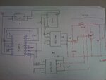
this is the schematic... DSC_1892_small.jpg
how can i apply dead time?

there are several mistakes when drawing the schematic. but i corrected it when applying on the board.
 

Well , TL494 has internally dead time matching . see page 8 of datasheet . with two resistor . by the way , do you know the aim of another IGBT that used as diode ? you can use a low power IGBT , and then use a high power diode in parallel with it's collector emitter to decrease the cost . it used to provide a path to charge the boot strap capacitor . so it won't has high current . the diode that is in parallel should be able to tolerate high currents . ( minus voltage ) .
BTW : you'd better to increase the value of boot strap capacitor . but it depends on the frequency of operation . how much is the frequency ?
I think the value of your out put capacitor is low too . how you designed them ? randomly ?
Good luck
Goldsmith
 

Well , TL494 has internally dead time matching . see page 8 of datasheet . with two resistor . by the way , do you know the aim of another IGBT that used as diode ? you can use a low power IGBT , and then use a high power diode in parallel with it's collector emitter to decrease the cost . it used to provide a path to charge the boot strap capacitor . so it won't has high current . the diode that is in parallel should be able to tolerate high currents . ( minus voltage ) .

the aim is for good efficiency right?

the IGBT i used for both switches for sync operation has anti parallel diode in it. i'm using this one. https://www.farnell.com/datasheets/34686.pdf
i did try the conventional buck converter yesterday.
but i fail to understand the reason why (i used an ultrafast diode to replace the second IGBT) the output current seems to remain when i..

1. remove the diode (when the circuit is still running). the diode seem to not be playing any role right?

2. remove the diode + inductor + capacitor. the LED still lit up. but of course, if with the cap, the LED lit brighter.

all of the two, i still could control the brightness with just the duty cycle only when the output voltage (at the LEDs) reaches the total voltage drop of the LEDs.

BTW : you'd better to increase the value of boot strap capacitor . but it depends on the frequency of operation . how much is the frequency ?
I think the value of your out put capacitor is low too . how you designed them ? randomly ?
Good luck
Goldsmith

the frequency is 50kHz. is 1uF enough? but it seems to be during the first few weeks of testing. that's why i'm confused why is it failing now :sad:

and i calculated the values first. then i proceeded to pick values around the values from calculation. for L and C i went for values larger than the ones i calculated. that should be alright right? i even increased the o/p cap to 22uF.
 

Hi again
I don't think that this IGBT is good for your aim . see page 3 of it's datasheet , please . why , IGBT ? why not mosfet ? for instance , if your input voltage isn't higher than 50 volts , an IRFZ44N can be a good choice . or if your voltage is higher , an IRFP450 or IRFP460 can be brilliant .
Are you familiar with basic of a buck converter , really ? if , no , i can describe it for you .
Anywhere , even you can use a simple bjt , in parallel with a fast diode , instead of , 2nd switch .
1. remove the diode (when the circuit is still running). the diode seem to not be playing any role right?
That diode , has two purpose , in this circuit :
1st one is , to keep the switch from minus and high voltage . the cause of this high voltage in minus polarity is lenz law .
If you see the voltage across the inductor , it will be an AC square wave .
2nd : to recharge the capacitor when the switch is off .
2. remove the diode + inductor + capacitor. the LED still lit up. but of course, if with the cap, the LED lit brighter.
Our eyes , can't understand , the frequencies , above 50 HZ . use an oscilloscope . ( smart eye of each engineer !! )
And about the LC filter at he out put , give me the value of your input voltage and maximum and minimum output voltage and current , thus i can help you in : how to design the out put filter .
There are two simple formula available .
Good luck
Goldsmith
 

why , IGBT ? why not mosfet ?
the design initially was suppose to carry out 240Vac and be rectified to the buck converter. but i have to scrap that when the sync buck wasn't working. (but it was perfectly fine the first week of testing, i wonder what happened). i guess that IGBT was appropriate for that.

Are you familiar with basic of a buck converter , really ? if , no , i can describe it for you .
Anywhere , even you can use a simple bjt , in parallel with a fast diode , instead of , 2nd switch .
i am familiar a bit with the basic buck theoretically. but i might understand it wrong. if it's okay maybe you describing it might clarify certain things i have doubts on.
That diode , has two purpose , in this circuit :
1st one is , to keep the switch from minus and high voltage . the cause of this high voltage in minus polarity is lenz law .
If you see the voltage across the inductor , it will be an AC square wave .
2nd : to recharge the capacitor when the switch is off .
Our eyes , can't understand , the frequencies , above 50 HZ . use an oscilloscope . ( smart eye of each engineer !! )
yes, i did saw the AC square wave at the inductor when i tried the normal buck converter. i'm carrying out the experiment again tomorrow, i'll capture some waveforms of the 2 cases i tried (with and without the diode)

And about the LC filter at he out put , give me the value of your input voltage and maximum and minimum output voltage and current
input voltage = 30 - 100V
o/p voltage = 7 LEDs, about 21-28V
o/p current = LED max current rating is 350mA. i guess it's about that value.

Thank you so much goldsmith for helping me out :-D
 

Hi again
At first , if you want achieve this voltage from 240 volts , it is possible , but be careful , this voltage is DC and means that it is , more dangerous than AC voltage . so , pay more attention to the safety .
And about IGBT : it can handle your aim , but not as well as possible . you can change it with better one , or you can use a mosfet , for instance , IRF740 . the VDSS of that is around 400 volts and ID= around 10 amperes and rdson is about 0.5 ohms ( approx ) .
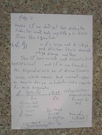
Well , i wrote 3 pages for you , read them and then if you have any problem , ask me again , please :


Best Wishes
Goldsmith
 

In addition to Goldsmith's recommendations...

You might like to look at my video on Youtube which portrays switched-coil converters in simulated animation. It includes the buck type.

www.youtube.com/watch?v=FT_sLF5Etm4
 
Hi again
And about IGBT : it can handle your aim , but not as well as possible . you can change it with better one , or you can use a mosfet , for instance , IRF740 . the VDSS of that is around 400 volts and ID= around 10 amperes and rdson is about 0.5 ohms ( approx ) .
Well , i wrote 3 pages for you , read them and then if you have any problem , ask me again , please :

thanks for explaining. i have several questions though. the calculated values are all minimum right? because i'm using 2mH and 22uF. that serves as a fillter, so my output should then have less ripple right? please correct me if i'm wrong.

i did capture several waveforms and i would like to ask you whether if i'm doing it right. should i email or put it up here?

i'll get the mosfet but before i can get my hands on the mosfet you suggested, i'm still using the igbt for today's tests.
thanks again, goldsmith. you're a great help.

In addition to Goldsmith's recommendations...

You might like to look at my video on Youtube which portrays switched-coil converters in simulated animation. It includes the buck type.

www.youtube.com/watch?v=FT_sLF5Etm4

the video did help understand a few stuff on the converter. thank you for sharing! :smile:
 

Glad my video helped.

A switched coil can create a high voltage kick.

Is it possible the system deteriorated in operation (even though it worked properly at the beginning), because the IGBT characteristics were altered by repeated kicks from the coil?
 

Is it possible the system deteriorated in operation (even though it worked properly at the beginning), because the IGBT characteristics were altered by repeated kicks from the coil?

i think that's probably it. that's why i think i'm gonna go get the mosfet goldsmith suggested me.
i'm pretty bumped out because it works perfectly in the beginning. now that it's near submission, it decides to fail me :-(

anyway, have you ever tried them practically?
 

i think that's probably it. that's why i think i'm gonna go get the mosfet goldsmith suggested me.
i'm pretty bumped out because it works perfectly in the beginning. now that it's near submission, it decides to fail me

anyway, have you ever tried them practically?

I have used mosfets in the IRF 540 and 740 family. I have burned up a few mosfets as I worked on a homemade inverter. It goes with the territory.

Remember to use precautions for static charge around a mosfet.

You may not need a heatsink. You're using it as a switch for under an amp of current. Nevertheless it's a good idea to check whether it overheats. Did you check as to whether your present device is running hot or cool?
 

Remember to use precautions for static charge around a mosfet.

You may not need a heatsink. You're using it as a switch for under an amp of current. Nevertheless it's a good idea to check whether it overheats. Did you check as to whether your present device is running hot or cool?

sorry for asking, but why need the precaution?

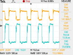
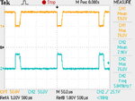
yes i always check whether if the IGBT or diode is heating up or not. i'm so afraid that they'll damage as i only have a few more left. the waveform of the diode voltage (top/yellow) and the voltage across the switch (below/blue) is as below. there's a spike after the diode voltage falls to zero. i think i have a problem with the bootstrapping or the inductor. but i'm not sure. what do you think?

30V_Vdiode vs Vce.JPG
 

Hi again
At first , about the values that i told , those are the best values for a buck converter with your specifications .
And about the attached waveform , i can see a little overlap , and it means that you have to increase dead time . and be sure if you increase dead time the problem will solve .
Best Wishes
Goldsmith
 

sorry for asking, but why need the precaution?

The insulated gate in MOS devices can be perforated by a sufficiently high voltage. When that happens it is likely to make the device unusable.

The advice is to wear a grounding strap to drain away static charge from your body when working around IG or MOS devices. (Or at least to touch something large and made of metal beforehand, which is what I do although I'm not saying that guarantees anything.)

Your waveforms do not seem to show severe spikes, because if they did then it would risk damaging your IGBT.

Also if your coil is 2mH, then consider running it at a lower frequency. Say 2 to 10 kHz. Try observing what it does at various frequencies, because a given henry value responds according to its time constant, as determined by resistance of the charge/discharge path.

Your coil will need time to charge through the mosfet. It takes about 5 time constants before it reaches maximum current. Say overall resistance is 2 ohms. Then it will need 5 x .002 / 2, or .005 second to charge up to maximum.

Of course you may not need to let it reach maximum current. It depends on how heavy a load you are powering.
 

Hi again
At first , about the values that i told , those are the best values for a buck converter with your specifications .
And about the attached waveform , i can see a little overlap , and it means that you have to increase dead time .
ok..
what about the 100uF? i've been using 1uF, is that not large enough, would that be better if i get a larger one than 100uF?
if i were to apply dead time, it should be at the IC 494 right?

Also if your coil is 2mH, then consider running it at a lower frequency. Say 2 to 10 kHz. Try observing what it does at various frequencies, because a given henry value responds according to its time constant, as determined by resistance of the charge/discharge path.

Your coil will need time to charge through the mosfet. It takes about 5 time constants before it reaches maximum current. Say overall resistance is 2 ohms. Then it will need 5 x .002 / 2, or .005 second to charge up to maximum.

i'm powering 7 LEDs. i think it's not really a heavy load..
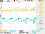
i tried lowering the frequency. i could only manage to get to 5kHz..this is what i got at 40kHz..the response is almost the same as at 5kHz(also, i did run it to input voltage of 60V. the previous one was at 30V)

60V_Vdiode vs. Vce.JPG
it seems to turn off accordingly, but then there's a problem with the turning on part. *sigh* i shall try again today.
by the way, if i increase the inductance, the frequency could go higher?

thanks to both of you :)
 

what about the 100uF? i've been using 1uF, is that not large enough, would that be better if i get a larger one than 100uF?

1uF is probably too low. It exhibits large voltage swings, and is liable to encourage ringing (parasitic) oscillations.

You mentioned 22uF at some point. That should be good for a light load. But there's nothing wrong with using 100uF.

if i increase the inductance, the frequency could go higher?

Higher henry value goes with a lower frequency.

You mentioned 50 kHz. This frequency goes with a henry value in the tens of uH (maybe a few hundreds of uH). This is an estimate based on simulations I've done, from observing that the transistor needs to be on for a long enough time, until the coil is passing sufficient current so that the load will continue to receive power through the transistor 'off' time.
 

1uF is probably too low. It exhibits large voltage swings, and is liable to encourage ringing (parasitic) oscillations.

You mentioned 22uF at some point. That should be good for a light load. But there's nothing wrong with using 100uF.
the bootstrap capacitor i'm using now is 100uF. it seems to be ok :)

for the output capacitor...
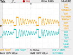
whenever i put any kind of capacitor at the output, this waveform will form Vce vs. Vdiode.JPG
but without any output capacitor, the output will be TEK0005.JPG so the average output voltage and current will be less.

-voltage across the switch (Vce/yellow) and voltage across diode (blue)

but my IGBT and diode isn't heating up.

Higher henry value goes with a lower frequency.

You mentioned 50 kHz. This frequency goes with a henry value in the tens of uH (maybe a few hundreds of uH). This is an estimate based on simulations I've done, from observing that the transistor needs to be on for a long enough time, until the coil is passing sufficient current so that the load will continue to receive power through the transistor 'off' time.
i tried with 800uH at 5kHz, the response this time is good. but like the above, without the capacitor, the waveforms seems to be ok.
 

i tried with 800uH at 5kHz, the response this time is good. b
Are you trying to select randomly ?? with events ??? it isn't design . you should learn , how to design . this way isn't correct and your value isn't correct too .
 

Status
Not open for further replies.

Part and Inventory Search

Welcome to EDABoard.com

Sponsor

Back
Top