Continue to Site

Welcome to EDAboard.com

Welcome to our site! EDAboard.com is an international Electronics Discussion Forum focused on EDA software, circuits, schematics, books, theory, papers, asic, pld, 8051, DSP, Network, RF, Analog Design, PCB, Service Manuals... and a whole lot more! To participate you need to register. Registration is free. Click here to register now.

Symmetrical OTA and ECG waveform

Status
Not open for further replies.

ehsanaiman

Junior Member level 2
Joined
Sep 17, 2017
Messages
22
Helped
0
Reputation
0
Reaction score
0
Trophy points
1
Location
Batu Pahat
Activity points
185
Hello, Im simulating symmetrical OTA/ 3 current mirror OTA as shown in figure below.
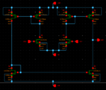
schematic90nm.PNG
The testbench as shown in figure below.
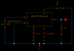
tb90nm.PNG
The circuit powered up by +/- 0.9V voltage source and the current source is 2uA. For the input, I use vpwlf which I can put ECG waveform input from MIT database.

But the output of ECG waveform as shown in figure below is not in the same shape of the input. Of course, this OTA should be amplify the ECG signal but I dont know why the shape also changed. Can anyone check this and help me?
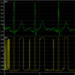
90nm ecg result.PNG
 

Calculate or measure the OTA gain.
Consider what's the maximum input voltage that can be processed undistorted.
How do you set the circuit gain? An OTA with capacitive load is acting as a low-pass rather than amplifier with well defined voltage gain.
 

Without degeneration, or any linearization the OTA transconductance is strongly dependent on input voltage amplitude. Your output is the result of huge and non-linear gain.
Use negative feedback somewhere to reduce gain and improve linearity.

By the way, if you have 0.7V input amplitude peaks with 2*0.6V supply why do you need an amplifier? And how can you get 0.8V and -0.8V levels at the output if the VDD and |VSS| is 0.6V?
Strange for me. Some infos are missing from here, like axis scaling.
 

The testbench as shown in figure below.

Regardless of the distortion cause, you should be aware that the above tesbench circuit does not faithfully represent the actual model of a human body, that is to say, it should be inserted a not negligible series impedance to the voltage source; depending on the arrangement of the feedback resistors, it may impact as an additional attenuation. Another point to consider is that the MIT database make use of signal input values with an average peak of about 1mV, which means that this should go through an input amplification stage, afaik not done with OTA, but OpAmp instead.
 

Hi andre_teprom, thanks for the explanation, Im aware about testbench not being same as human actual body. This is just a small simulation to validate the OTA circuit.

You said that input amplification stage should be done with Opamp, but most of papers doing OTA as their amplifier circuit? Im quite confused, the amplification of OTA is not same as the Opamp amplification?

And what is most suitable opamp topology used to amplify biopotential signals as this paper "A Low-Power Low-Noise CMOS Amplifier for Neural Recording Applications" by Reig Harrison is using same topology OTA with the one that Ive tried to simulate.

- - - Updated - - -

Without degeneration, or any linearization the OTA transconductance is strongly dependent on input voltage amplitude. Your output is the result of huge and non-linear gain.
Use negative feedback somewhere to reduce gain and improve linearity.

By the way, if you have 0.7V input amplitude peaks with 2*0.6V supply why do you need an amplifier? And how can you get 0.8V and -0.8V levels at the output if the VDD and |VSS| is 0.6V?
Strange for me. Some infos are missing from here, like axis scaling.

I dont know how to do axis scaling in Waveview and the input ECG waveform is in mV ranges.

- - - Updated - - -

Calculate or measure the OTA gain.
Consider what's the maximum input voltage that can be processed undistorted.
How do you set the circuit gain? An OTA with capacitive load is acting as a low-pass rather than amplifier with well defined voltage gain.

So i have to discard the capacitive load in order to make OTA into amplifier with voltage gain?
 

So i have to discard the capacitive load in order to make OTA into amplifier with voltage gain?
Capacitive load will be present in any real circuit. The problem is that the circuit has no means to set up a defined gain, either feedback or a respective real load.

but most of papers doing OTA as their amplifier circuit
Did you study the amplifier circuits implemented in this papers?
 

I dont know how to do axis scaling in Waveview and the input ECG waveform is in mV ranges.
And what is the output voltage scaling? I assume it is mV too, so your circuit is not fast enough either. Also share please the time axis scaling.
The paper you mentioned uses capacitive feedback to set the gain and "resistive" feedback to set the DC operating point. In your testbench those are missing.
I think you can use OTAs in a cascaded configuration where negative feedback is present and capacitive feedback isn't necessary. The advantage of the OTA it is voltage controlled, so the source resistance of the body shouldn't be a problem, and the current consumption, area should be the smallest with OTAs, but a non-inverting amplifier with an OPAmp(s) also can achieve these.
 

Status
Not open for further replies.

Part and Inventory Search

Welcome to EDABoard.com

Sponsor

Back
Top