Welcome to our site! EDAboard.com is an international Electronics Discussion Forum focused on EDA software, circuits, schematics, books, theory, papers, asic, pld, 8051, DSP, Network, RF, Analog Design, PCB, Service Manuals... and a whole lot more! To participate you need to register. Registration is free. Click here to register now.
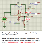
Your math is off. :wink: You apparently forgot about how R7 and R8 affect the non-inverting gain.
The voltage at the op amp (+) input is 2.5V, multiplied by the gain of the op amp, which is +2 (due to R7 and R8), giving an output of +5V for that input
The +7V at the minus input is multiplied by the op amp gain of -1, giving an output of -7V for that input.
Using superposition, the op amp output is thus -2V, exactly as you simulated.
This site uses cookies to help personalise content, tailor your experience and to keep you logged in if you register.
By continuing to use this site, you are consenting to our use of cookies.