Continue to Site

Welcome to EDAboard.com

Welcome to our site! EDAboard.com is an international Electronics Discussion Forum focused on EDA software, circuits, schematics, books, theory, papers, asic, pld, 8051, DSP, Network, RF, Analog Design, PCB, Service Manuals... and a whole lot more! To participate you need to register. Registration is free. Click here to register now.

subthreshold n factor

Status
Not open for further replies.

iexplorer

Member level 3
Joined
Aug 8, 2007
Messages
63
Helped
0
Reputation
0
Reaction score
0
Trophy points
1,286
Activity points
1,646
Does anyone know if the subthreshold n factor in (I=It exp((VGS-VTH)/(nVT))) has large variation with process corner and temperature? And also is the n factor the same in parasitic BJT current equation? Thanks!
 

iexplorer, hi!

If you have any PDK with monte carlo section , you can simulate it.
without factory measurements its difficult to know.

Best reguards
 

Subthreshold slope in some models is driven by NSS (number of surface states)
and this goes directly to oxide quality, driven by cleanliness and the finish of
the gate ox process and subsequent thermal budget and hydrogen passivation
and whether the passivation remains stable or is modified by things like voltage
stress, radiation, etc. Devices with bird's beak or trench oxide quality issues
show "gate kink" in subthreshold, an expression of the physical nonuniformity
of the channel.

So it can be very variable. It is also in my experience not especially well
modeled to begin with, particularly if nobody stands up for analog fidelity
when the modeling guys are trying to call it "done". The corner from
subthreshold to strong inversion is problematic, simulators depend on
some "fudge factor" params to get the transition reasonably right. In
fitting models myself, I've seen the transition params capable of making
some crazy Id-Vgs results and also of producing singularities if taken
too far.

Subthreshold slope is something I have to fight to get added to WAT
lists, it stands a good chance of not being controlled or even monitored.
In this case the modeling group hasn't even got statistics to work from
and MC analysis may show no variation at all as a result.
 

Hi iexplorer!

I have simulated the subthreshold factor "n" and it depends on the temperature. But the variation is not so significant. Its value is nearly 1.2 [V], and varies some milivolts around it for a large temp. range (-40 to 124 ºC).
Regarding the process dependency, for sure "n" depends on it. It mainly depends on “tox” and “gamma”. But, for hand-analysis purposes, this variation is not significant as well and I would be worry about it. This is my point of view.

Regards,
 

I have simulated the subthreshold factor "n" and it depends on the temperature. But the variation is not so significant. Its value is nearly 1.2 [V], and varies some milivolts around it for a large temp. range (-40 to 124 ºC).
Regarding the process dependency, for sure "n" depends on it.

Hi palmeiras,

from David M. Binkley's book "Tradeoffs and Optimization in Analog CMOS Design" I've extracted some tables on the substrate factor n dependency on processes, Inversion Coefficient, and temperature. May be it's helpful: View attachment substrate-factor__Binkley.pdf
 
Hi palmeiras,

from David M. Binkley's book "Tradeoffs and Optimization in Analog CMOS Design" I've extracted some tables on the substrate factor n dependency on processes, Inversion Coefficient, and temperature. May be it's helpful: View attachment 60749

Hi erikl,
could you tell me how to make a chart of gm/id vs. inversion coefficient with Spice or Spectre? I just can't get the inversion coefficient curve, because some parameters like u0,cox and n, i can't get from the pdk model documents.

Regards,
 

Binkley uses the so-called "fixed-normalized" inversion coefficient (IC), which can be calculated from the drain current ID and the MOSFET's W/L ratio, if the technology current I0 is known, s. the following page from Binkley's book: View attachment Binkley__substrate_factor_p47.pdf

If you can't get those parameters, for an approximation you could perhaps use the values for a similar process of yours, see the foll. 2 pages from the same book: View attachment Binkley__tech_parameters_pp42-43.pdf
 

Hi iexplorer!

I have simulated the subthreshold factor "n" and it depends on the temperature. But the variation is not so significant. Its value is nearly 1.2 [V], and varies some milivolts around it for a large temp. range (-40 to 124 ºC).
Regarding the process dependency, for sure "n" depends on it. It mainly depends on “tox” and “gamma”. But, for hand-analysis purposes, this variation is not significant as well and I would be worry about it. This is my point of view.

Regards,


Ops.... I´m sorry. The subthreshold factor "n" is dimensionless, and it varies a little bit (in the order of 1.2/1000) in the temperature range. Regards.
 

Hi palmeiras,

from David M. Binkley's book "Tradeoffs and Optimization in Analog CMOS Design" I've extracted some tables on the substrate factor n dependency on processes, Inversion Coefficient, and temperature. May be it's helpful: View attachment 60749

could u pls explain the significance of this parameter when used in the equation to find linear range of an OTA operated in subthreshold regime. the equation goes like this

Vl= 2*Φ / k : Vl-linear voltage range, Φ-thermal voltage , k- sub-threshold exponential parameter. the calculation yeilds to Vl= 80mv as per the paper. We know that Φ=25.9mv so the value of k yields to be 0.64. but am confused with the term that you represent here as substrate factor and k the sub-threshold exponential parameter. could pls explain this if possible with equations..

thanks in advance
 

... equation to find linear range of an OTA operated in subthreshold regime. the equation goes like this Vl= 2*Φ / k
: Vl-linear voltage range, Φ-thermal voltage , k- sub-threshold exponential parameter. the calculation yeilds to Vl= 80mv as per the paper. We know that Φ=25.9mv so the value of k yields to be 0.64.
Where did you find this equation?

... am confused with the term that you represent here as substrate factor and k the sub-threshold exponential parameter. could pls explain this if possible with equations..

I'd think your sub-threshold exponential parameter k corresponds to the subthreshold gate coupling coefficient κ of the EKV model, which is κ = UT/n (UT=Φ in your above equation), see e.g. R.R. Harrison: The MOS Transistor in Weak Inversion, p. 12 .
 
Where did you find this equation?
I got the equation from the journal "An Area and Power efficient analog Li-Ion Battery Charger" the equation was used to represent the linear range of sub-threshold operated OTA.


I'd think your sub-threshold exponential parameter k corresponds to the subthreshold gate coupling coefficient κ of the EKV model, which is κ = UT/n (UT=Φ in your above equation), see e.g. R.R. Harrison: The MOS Transistor in Weak Inversion, p. 12 .

as u mentioned sub-threshold exponential parameter k does not corresponds to the subthreshold gate coupling coefficient κ of the EKV model: thanks for the clarification but as per the paper u have suggested can it be k=1/n : "Some texts use n or ζ (zeta) instead of κ, where n = ζ = (1/κ) ≅ 1.4" n corresponding to substrate parameter in EKV model

i attach the page of the journal along with this post
 

Attachments

  • Capture1.PNG
    Capture1.PNG
    470.8 KB · Views: 102

... as per the paper u have suggested can it be k=1/n : "Some texts use n or ζ (zeta) instead of κ, where n = ζ = (1/κ) ≅ 1.4" n corresponding to substrate parameter in EKV model

i attach the page of the journal along with this post
Thank you for this page - unfortunately it isn't possible to follow up where this equation is stemming from: literature [7]?

With your above statement k=1/n you could be right - at least its size makes this plausible.

I had mixed up the subthreshold slope parameter n of the Harrison paper, see Wikipedia's subthreshold slope explanation - there named Ss-th, which gives the voltage necessary for getting the 10-fold current, i.e. mV/dec - with the substrate factor n, which you are using, sorry!

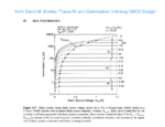
You might also want to see this saturation voltage vs. strong/medium/weak inversion diagram from D.M. Binkley's book: Binkley__saturation_voltage_p92.png.
Of course this is valid for a special W/L NMOS in a 0.18µm process, but you can approximately scale it for your special MOSFET.
 
Status
Not open for further replies.

Part and Inventory Search

Welcome to EDABoard.com

Sponsor

Back
Top