Vermes
Advanced Member level 4

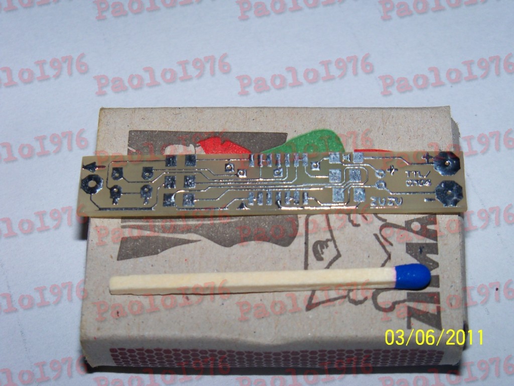
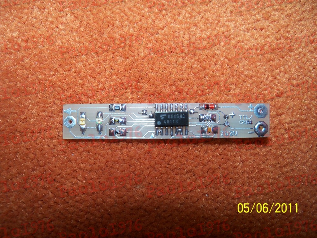
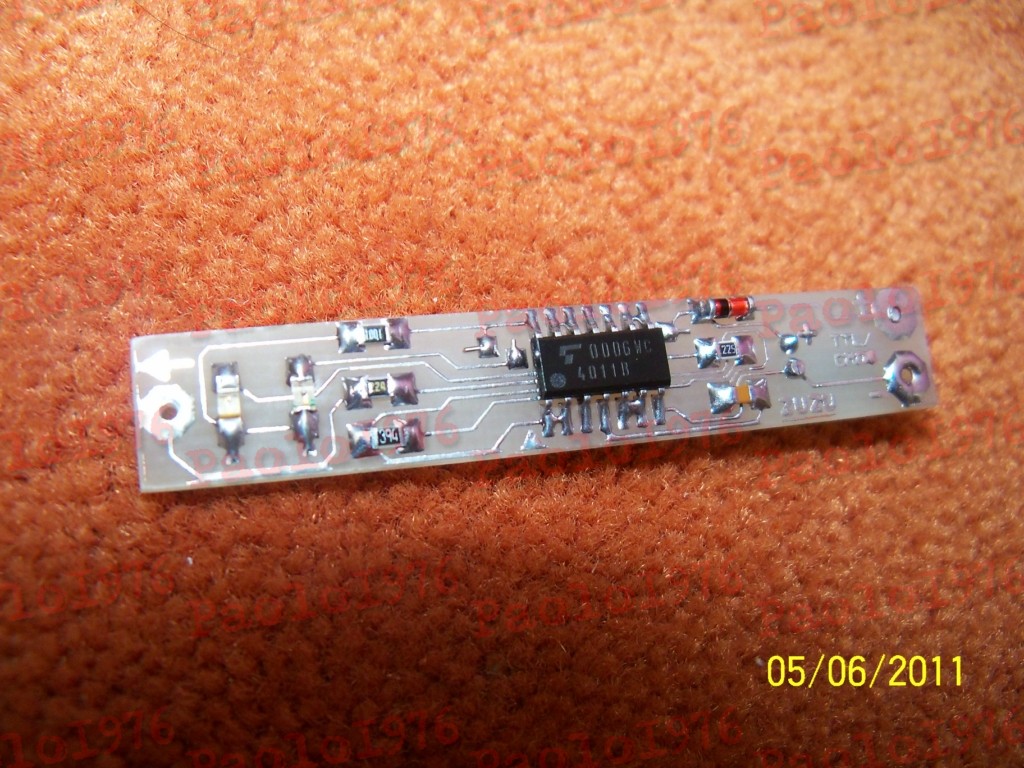
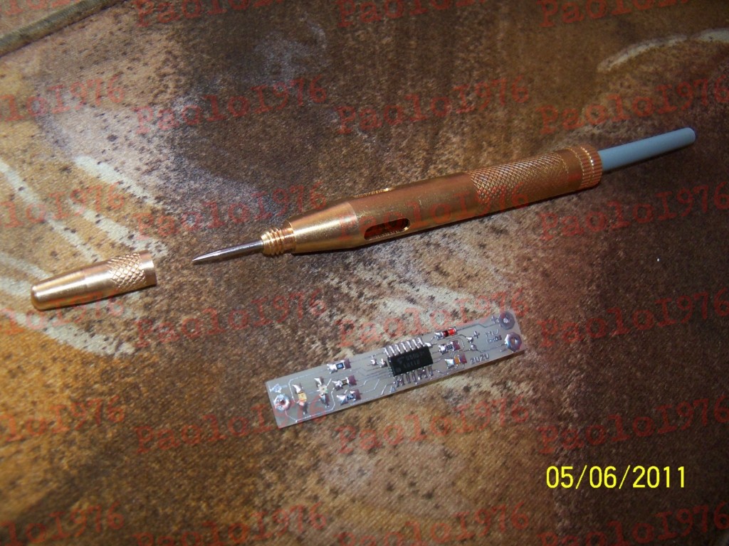
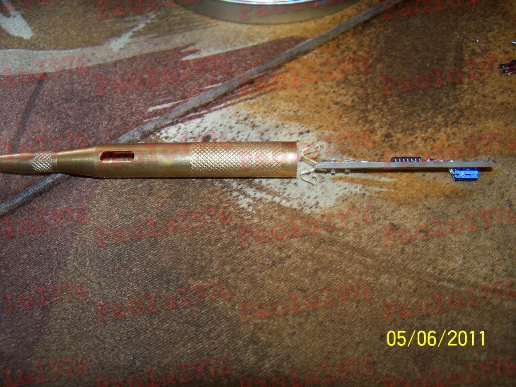
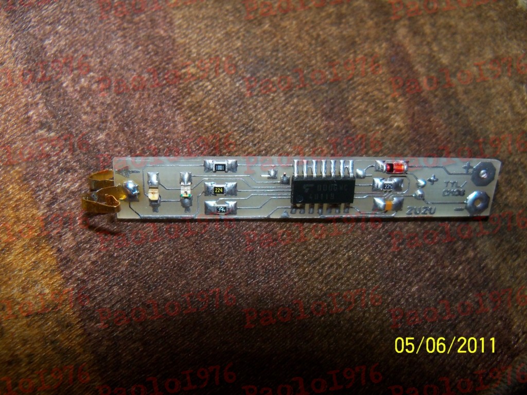
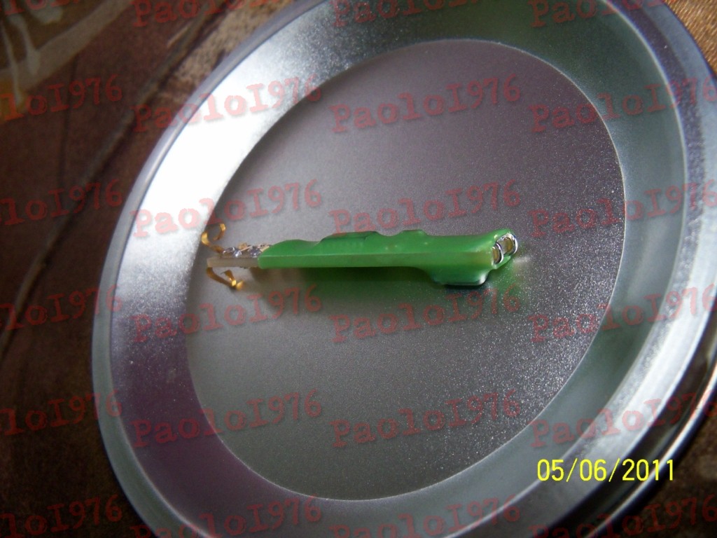
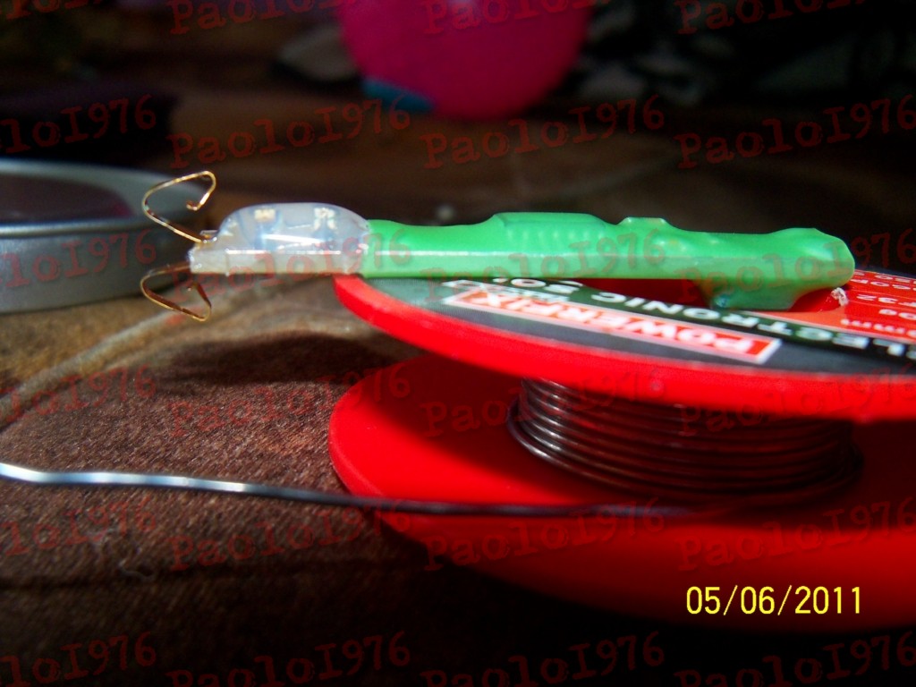
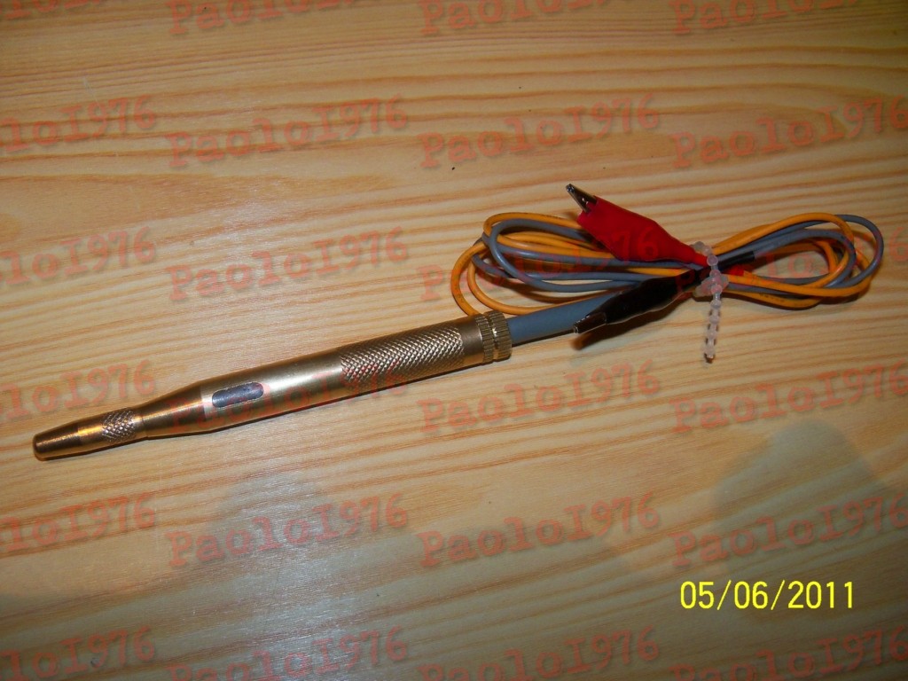
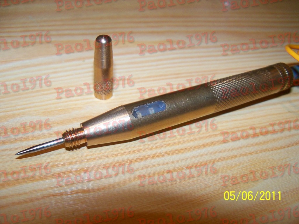
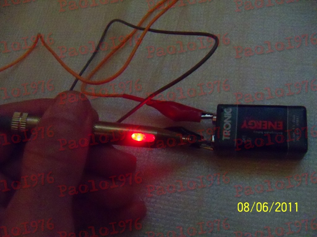
It is an indicator of logic states TTL/CMOS. The housing was made of a car voltage 6-24V tester in a very solid brass housing, with a sharp, precise measurement needle made of stainless steel, tucked under a solid, screwed cap. There was a little space inside – only a bulb of a size similar to a car fuse could fit. That is why the electronics had to be miniaturized.
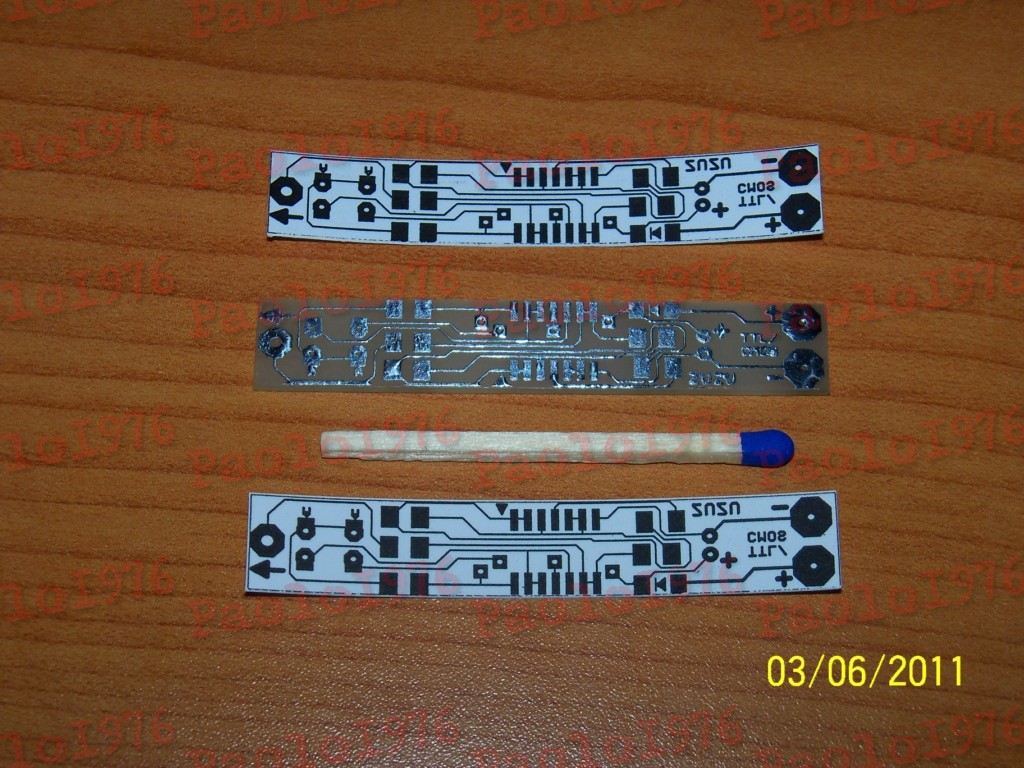
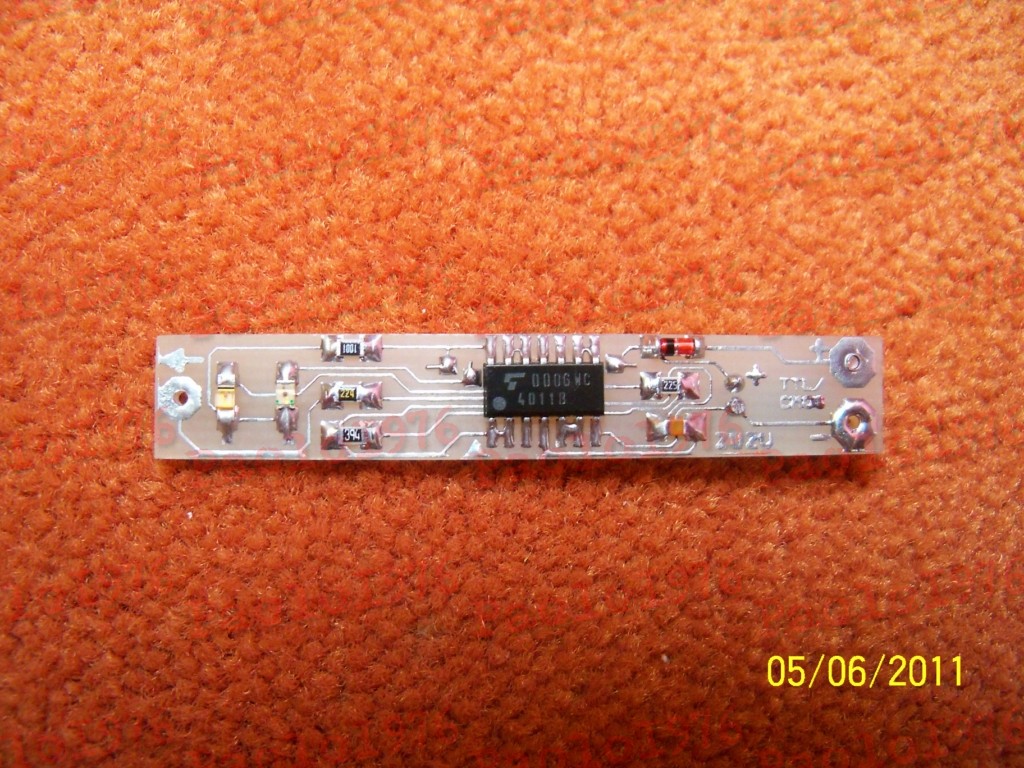
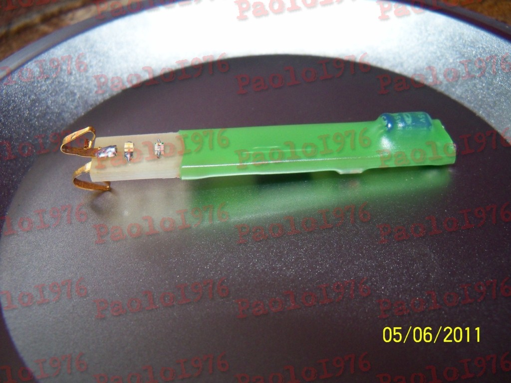
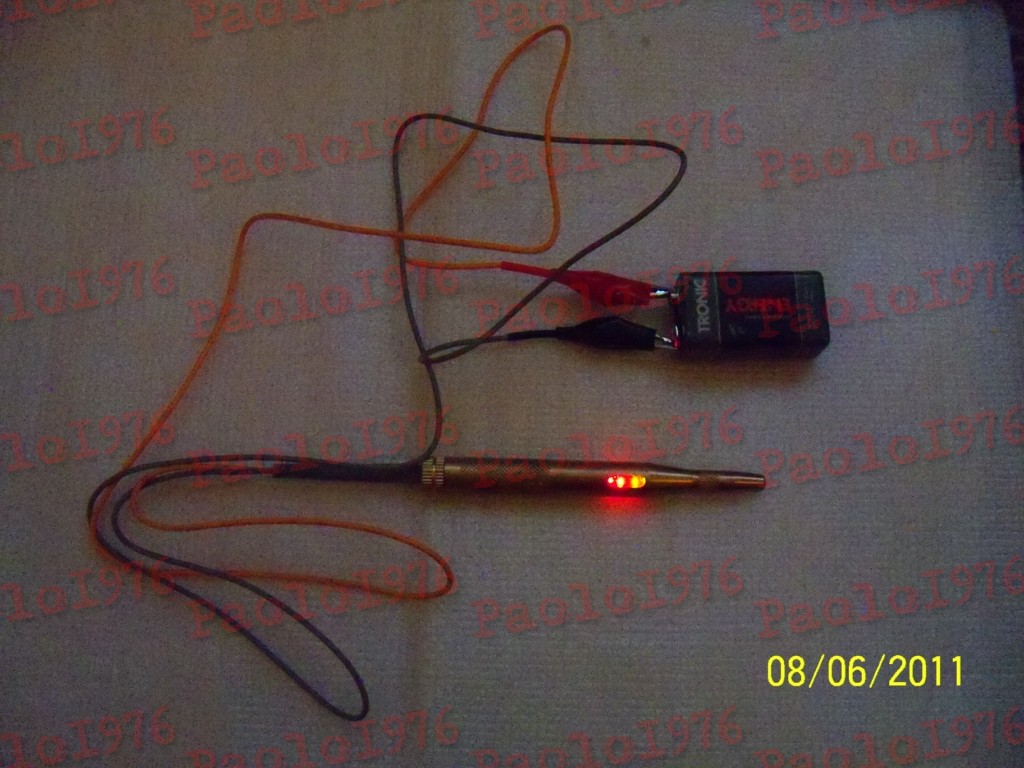
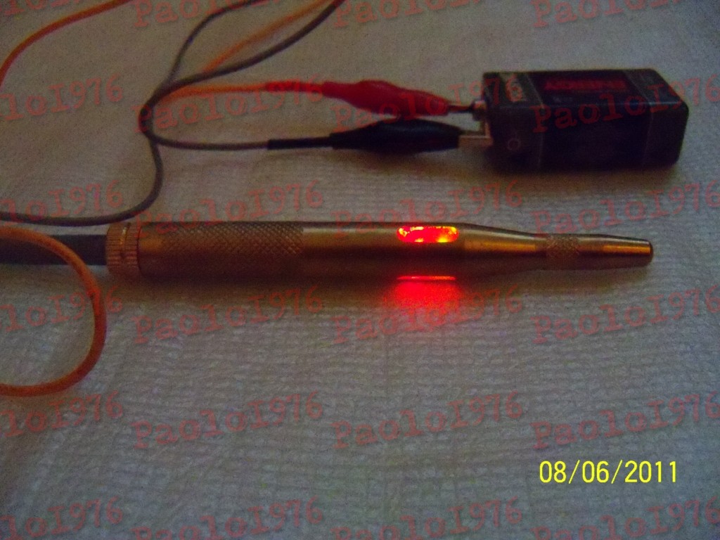
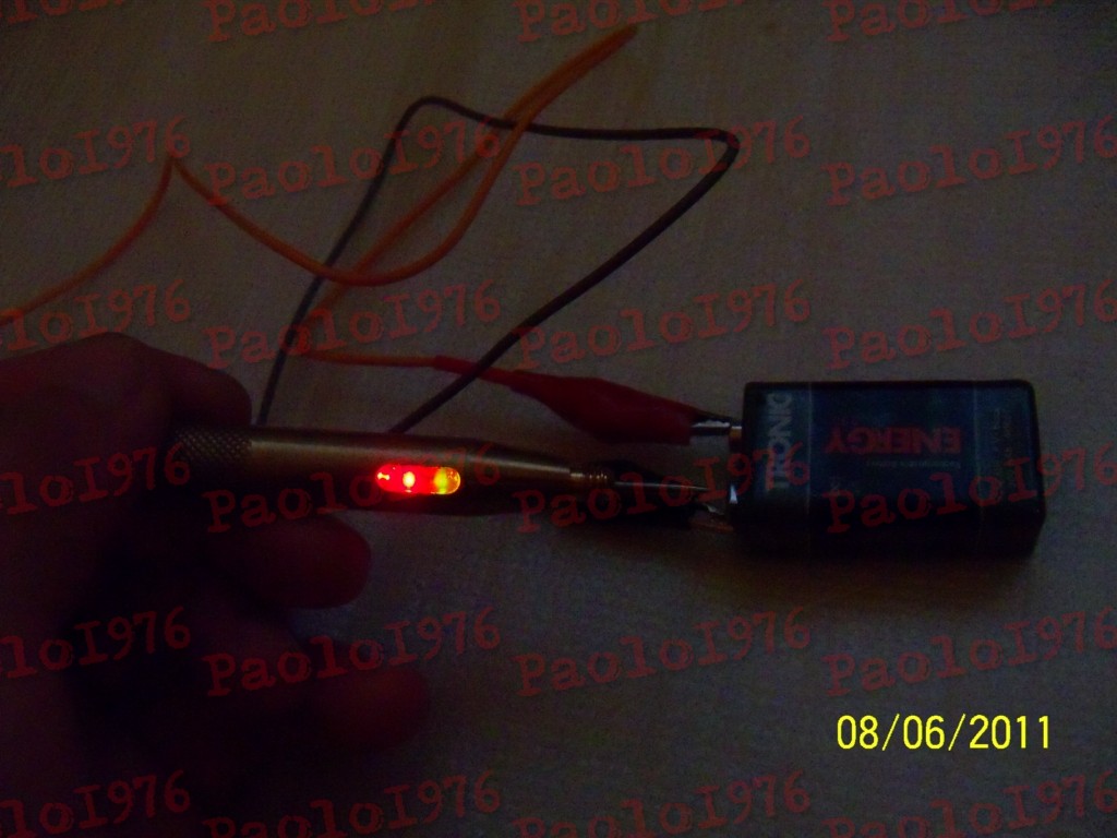
The PCB was designed in Cadsoft Eagle 5.10.0. Size of the board was 8mm x 50mm. SMD technology was used, 0,1mm paths made by thermal transfer iron method and tin-plated 50W by an old transformer soldering iron. Windows with LEDs were filled with hot adhesive, which after cooling was sanded with a cloth dampened with nitro solvent. This results in the fact that adhesive is all equally with the housing. There are no inequalities, and in “panes” of adhesive, LED light spreads ideal, making the indications very clear and intuitive. Some of the pictures were made without flash and with greater sensitivity to show that the LEDs light very strong and evenly.
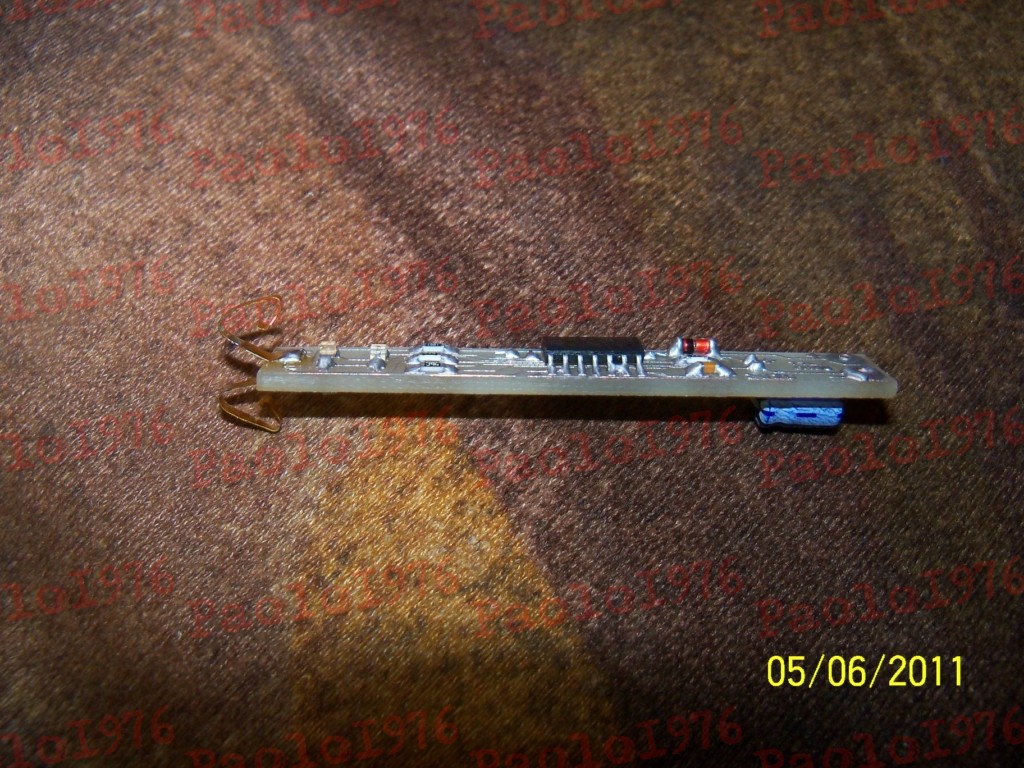
Measuring pad is connected to the housing by means of two quite springing, gilded “whiskers” (battery contacts from an old camera), which makes it easy to slide the PCB. The indicator is powered by the tested system, so there is no need to use an additional power supply. Simply plug in with the wires terminated with two small alligator clips. Grey tube is the silicone roll from the CD tray of the Sony car record player. It works perfectly as an element preventing the wires from breaking.
The indicator shows three states:
- red LED – logic 0
- green LED – logic 1
- red + green LED – transient or no signal at the input


Link to original thread (useful attachment) – Subminiaturowy tester stanów logicznych TTL/CMOS
Last edited: