Vermes
Advanced Member level 4
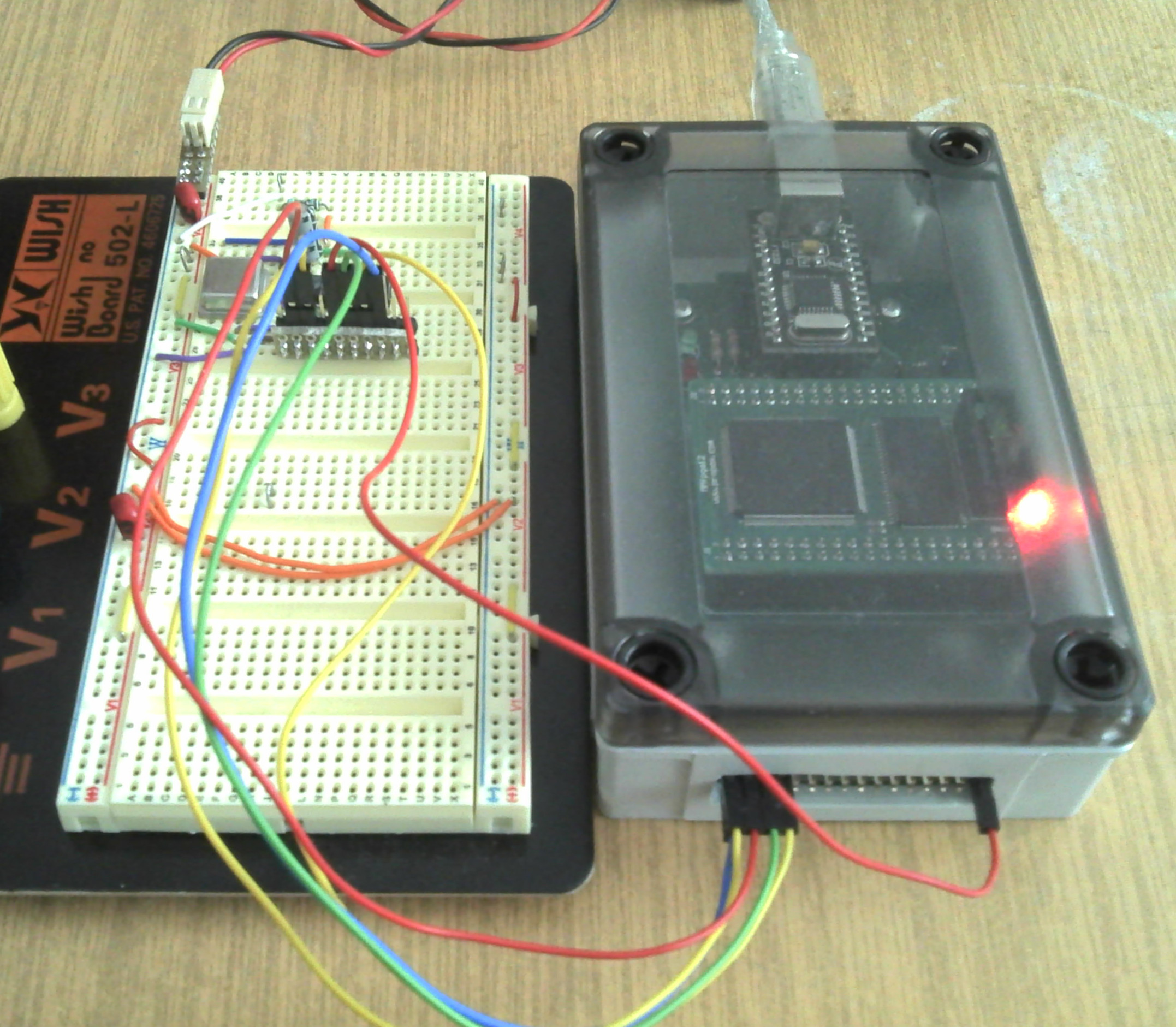
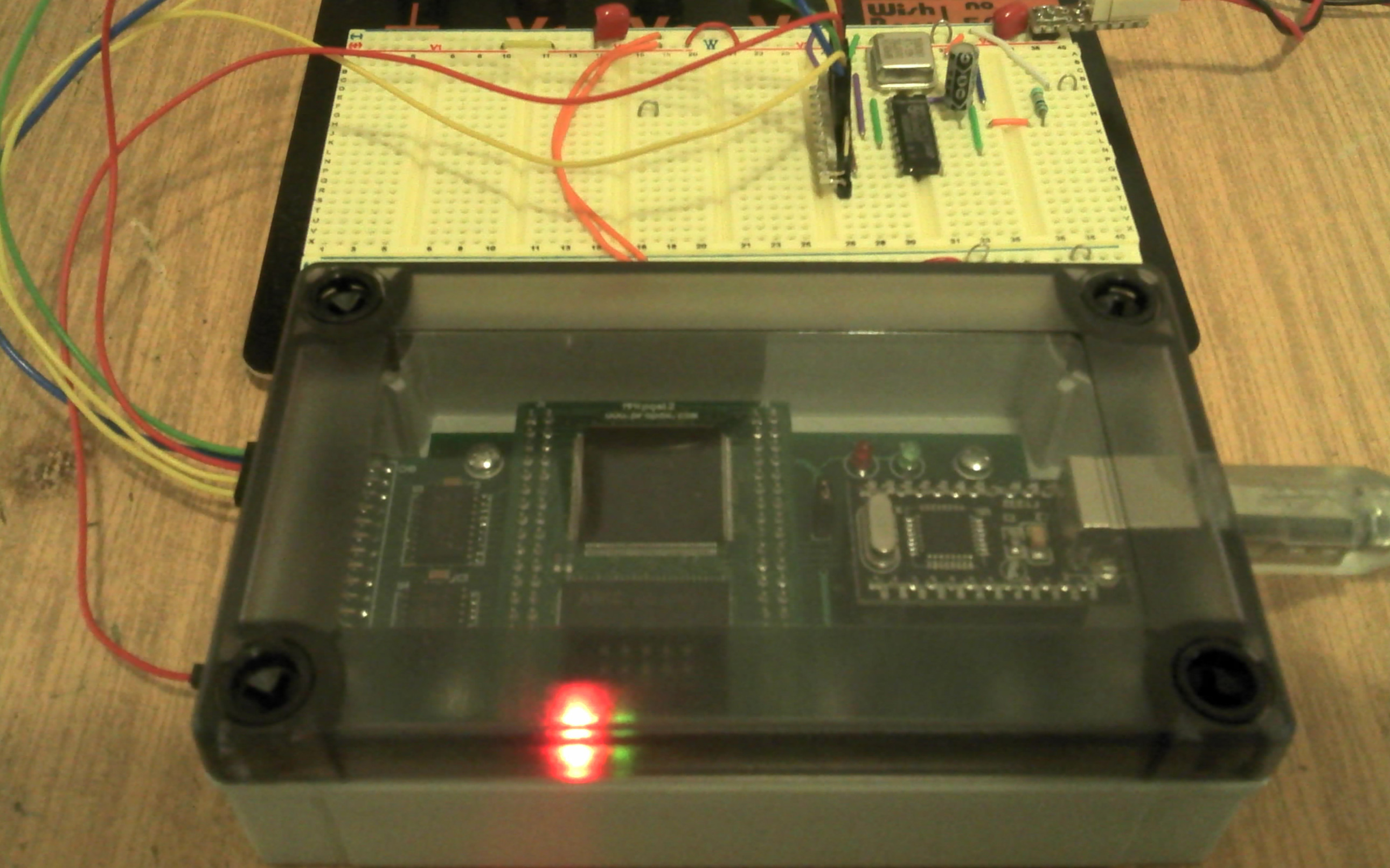
It is a logic state analyzer – very useful while running digital devices.
Basic parameters:
- 16 channels
- sampling frequency: 100 MSPS
- buffer capacity: 2048 samples
- range of input voltages: 0-5V
- frequency measurement: 0 – about 100 MHz
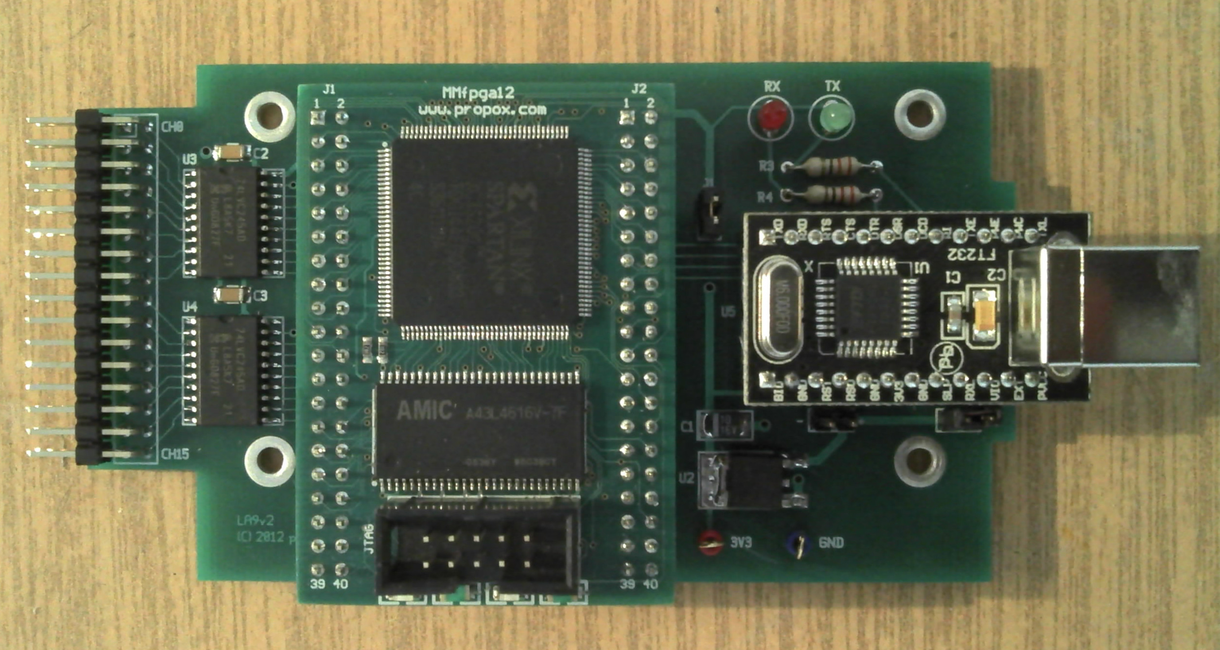
The analyzer is based on the following modules:
- Mmfpga12; module with FPGA XC3S200 and (currently not used) 64 Mb SDRAM and 4Mb Flash
- ZL2USB; module of communication with the USB
FPGA outputs are protected by two 8-bit buffers 74LVC245 with acceptable input voltage 5V, powered by 3,3V.
In the above pictures, the analyzer is connected with output signals of the counter 74HC193 controlled by signal 20 MHz.
The analyzer is controlled from a computer by means of two programs (digital signal record, frequency measurement on channel 15). Below you can see some examples of start.
Display the waveforms of recorded signals on the console:
Code:
$ ./la9 -d /dev/ttyUSB0 -n 16 0101 h:2 l:2*
[000]* * * *50 ns 0000000000000000 00 00*
[001]* * * 100 ns 0000000000000001 00 01*
[002]* * * 150 ns 0000000000000010 00 10*
[003]* * * 200 ns 0000000000000011 00 11*
[004]* * * 250 ns 0000000000000100 01 00*
[005]* * * 300 ns 0000000000000101 01 01*
[006]* * * 350 ns 0000000000000110 01 10*
[007]* * * 400 ns 0000000000000111 01 11*
[008]* * * 450 ns 0000000000001000 10 00*
[009]* * * 500 ns 0000000000001001 10 01*
[00A]* * * 550 ns 0000000000001010 10 10*
[00B]* * * 600 ns 0000000000001011 10 11*
[00C]* * * 650 ns 0000000000001100 11 00*
[00D]* * * 700 ns 0000000000001101 11 01*
[00E]* * * 750 ns 0000000000001110 11 10*
[00F]* * * 800 ns 0000000000001111 11 11*
[010]* * * 850 ns 0000000000000000 00 00*
[011]* * * 900 ns 0000000000000001 00 01*
[012]* * * 950 ns 0000000000000010 00 10*
[013]* * *1000 ns 0000000000000011 00 11*
[014]* * *1050 ns 0000000000000100 01 00*
start: 015*
Save the recorded signals in the file:
Code:
$ ./la9 -d /dev/ttyUSB0 -n 32 -o /tmp/counter.vcd 0101 q:4*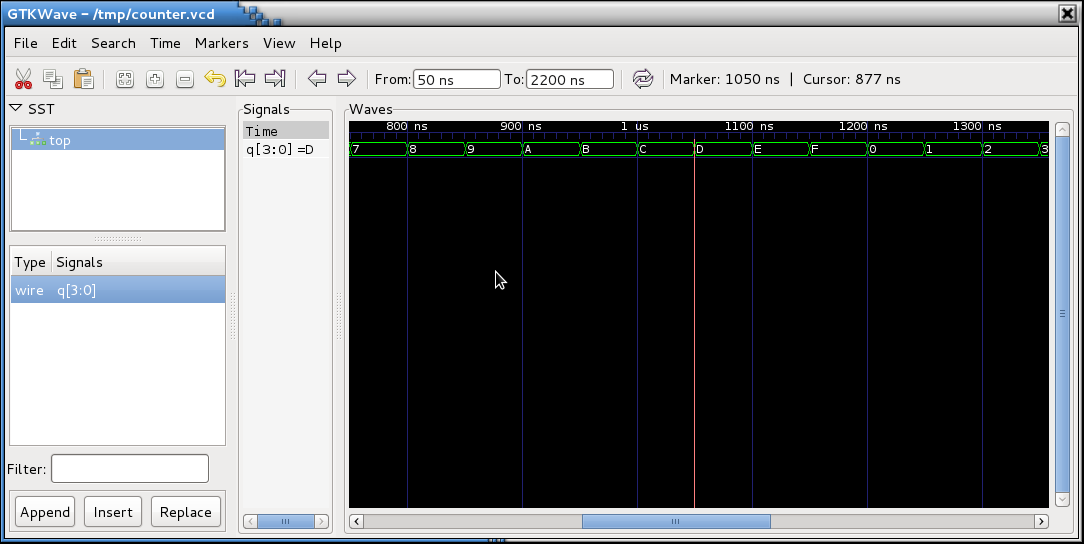
Measurement of frequency (reference frequency is 48 MHz):
Code:
$ ./la9freq -d /dev/ttyUSB0 -n 47999999*
19997194 Hz*
As you can see – the time of the open gate can be set according to your needs. Thanks to that, the device can be calibrated when you have the access to the frequency model.
Link to original thread - Analizator stanów logicznych