jerryvikram
Newbie level 3
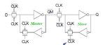
Hi, I've written a structural code for DFF, using Transmission gates. The diagram is attached. But when i tried to simulate in iSim , i did not get the output rather i got the message that :more than 10000 iterations. What is wrong here?
library IEEE;
use IEEE.STD_LOGIC_1164.ALL;
entity DFF is
port (
Clk : in std_logic;
D : in std_logic;
Q : out std_logic
);
end DFF;
architecture structural of DFF is
component Tx_Gate
port (
sel : in std_logic;
selbar: in std_logic;
ip : in std_logic;
op : out std_logic);
end component;
component not1
port (
ip : in std_logic;
op : out std_logic);
end component;
for Tx_Gate_1, Tx_Gate_2, Tx_Gate_3, Tx_Gate_4 : Tx_Gate use entity work.Tx_Gate(structural);
for not_1,not_2,not_3,not_4,not_5 : not1 use entity work.not1(structural);
signal ClkBar,n1,n2,n3,n4,n5,n6 : std_logic;
begin
Q <= n5;
not_1 : not1 port map(Clk,ClkBar);
Tx_Gate_1 : Tx_Gate port map(Clk,ClkBar,D,n1);
Tx_Gate_2 : Tx_Gate port map(ClkBar,Clk,n3,n1);
not_2 : not1 port map(n1,n2);
not_3 : not1 port map(n2,n3);
Tx_Gate_3 : Tx_Gate port map(Clk,ClkBar,n2,n4);
Tx_Gate_4 : Tx_Gate port map(ClkBar,Clk,n6,n4);
not_4 : not1 port map(n4,n5);
not_5 : not1 port map(n5,n6);
end structural;