Continue to Site

Welcome to EDAboard.com

Welcome to our site! EDAboard.com is an international Electronics Discussion Forum focused on EDA software, circuits, schematics, books, theory, papers, asic, pld, 8051, DSP, Network, RF, Analog Design, PCB, Service Manuals... and a whole lot more! To participate you need to register. Registration is free. Click here to register now.

Steady state error between type 1 and type 2 compensator

Patrick_66

Member level 3
Joined
Nov 18, 2023
Messages
60
Helped
0
Reputation
0
Reaction score
0
Trophy points
6
Activity points
408
Hello everyone,

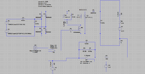
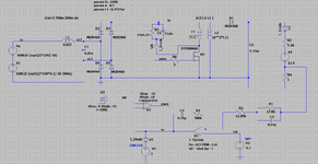
Currently I'm trying to simulate an LED driver with flyback configuration in DCM mode.
The output current is around 0.7A with 18W output power.

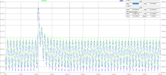
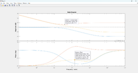
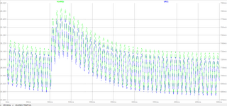
The problem that I'm currently facing is that the time to reach steady state is higher when using a type 3 compensator compared to a type two compensator. Wanted to know whether this is normal or wrong because if not mistaken using type 3 compensator is better for the overall performance of the system.

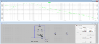
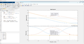
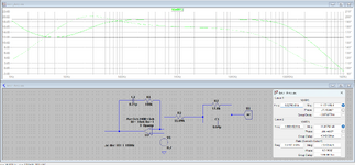
The system has a phase margin of 90 degrees when using a type 2 compensator whereas the phase margin is around 125 degrees when using a type 3 compensator and both having the same cross-over frequency. The figure of the circuit and simulation is shown below.

Hope that you can enlighten me and correct my mistake.
Thank you in advance for the help.

Type_2.png
Type_2_Waveform.png


Type_3.png
Type_3_Waveform.png
 
Delay is a f() of the pole-zero locations, so a broad statement about settling
time seems best served doing a design/analysis and calculating/simulating
settling time, which I see you seem to be doing.


Regards, Dana.
Hello Sir, as of now does my simulation make sense? Is it normal to have a system which longer transient response for type 3 compensator compared to type 2 compensator?
 
Type II and Type 3 can both be designed to tradeoff speed and for settling time
to some final value. Designer determines what results they want. A lead lag (Type III)
compensator can improve both speed and steady state, again designer
chooses that by positioning pole-zeros.


Regards, Dana.
 
Estimate the Poles from your RC=Tau (T) values and compare. Your two Types examples, I think do not use the same values.
A larger T for the partial integrator will increase settling time. Choosing filter response with critical damping (Butterworth) or no overshoot (Bessel) or higher BW ( faster response time) as maybe a way to set your goals. These are also tradeoffs with stability, step response error or interference error. This is the same as the methods to compute optimal PID constants Kp, Ki, Kd. Generally ultra-low ESR is a critical factor for ripple with gain which affects filter pole for optimal results. You get to define between what is optimal and what is possible.

This is a not an answer, but a heads-up on how to analyze your filter with different methods for time and frequency domain (Bode or Root Loci)
 
Last edited:
Estimate the Poles from your RC=Tau (T) values and compare. Your two Types examples, I think do not use the same values.
A larger T for the partial integrator will increase settling time. Choosing filter response with critical damping (Butterworth) or no overshoot (Bessel) or higher BW ( faster response time) as maybe a way to set your goals. These are also tradeoffs with stability, step response error or interference error. This is the same as the methods to compute optimal PID constants Kp, Ki, Kd. Generally ultra-low ESR is a critical factor for ripple with gain which affects filter pole for optimal results. You get to define between what is optimal and what is possible.

This is a not an answer, but a heads-up on how to analyze your filter with different methods for time and frequency domain (Bode or Root Loci)
Hello sir i use this way to analyse the compensator with the transfer function of the flyback with PWM. Is this the correct way of doing it?
 

Attachments

  • Type 2 Diagram.png
    Type 2 Diagram.png
    58.2 KB · Views: 29
  • Type 2 error.png
    Type 2 error.png
    87.2 KB · Views: 28
  • Type 2 Freq Response.png
    Type 2 Freq Response.png
    154.8 KB · Views: 29
  • Type 2 Waveform.png
    Type 2 Waveform.png
    73.9 KB · Views: 25
  • Type 3 diagram.png
    Type 3 diagram.png
    61.9 KB · Views: 27
  • type 3 Error.png
    type 3 Error.png
    97.7 KB · Views: 25
  • Type 3 Freq Response.png
    Type 3 Freq Response.png
    97.8 KB · Views: 25
  • Type 3 Waveform.png
    Type 3 Waveform.png
    67.7 KB · Views: 28

LaTeX Commands Quick-Menu:

Similar threads

Part and Inventory Search

Welcome to EDABoard.com

Sponsor

Back
Top